This tutorial will cover all of the steps necessary to flash an ESP device with ESPTool using a Raspberry Pi. The device I shall be flashing is a MagicHome RGB LED controller.
It is a ubiquitous design that comes in several flavours, usually branded as Arilux. However this tutorial can easily be adapted to work with any ESP-based device.
The Raspberry Pi is an ingenious little device and has many uses. Every enthusiast would benefit greatly from keeping a spare tucked away in a draw. In need of a new Pi? Click here to check the latest price of the newest and super-powerful Pi 4.
In this tutorial we will make use of the highly useful GPIO port on the Pi, as two of these pins share their function with the serial port. This means the Pi can communicate with devices that also have a serial port.
Devices such as ESP devices have a serial bootloader that allows the new firmware to be sent over the serial connection.
The chip does in fact flash itself with the firmware we deliver to it over the serial port, using its own bootloader firmware. The tool we will use to transfer our firmware is ESPTool.
In order to flash your device with your Pi, you will need to be able to access the circuit board inside and its likely you will need to solder some wires to the board.
Some ESP devices can be flashed over the air or via USB. If you cannot open up your device to access the circuit inside or you want to try to avoid soldering, take a look at the tutorial on how to flash Tasmota over the air.
If you are using a device like the Wemos D1 Mini that has a USB port, take a look at the tutorial for flashing over USB.
If you are new to Tasmota and you want to better understand some of its features and benefits, check out this article on the Tasmota and the cloud-free smart home.
Prerequisite
In order to complete this tutorial, you will need the following:
- Raspberry Pi with the Raspbian operating system
- An ESP device to flash
- An old RC servo lead or jumper wires
- Soldering iron and some solder
- A computer for SSH, or a screen, keyboard and mouse for your Pi
Preparing the Raspberry Pi
If you are using your Pi as a Home Assistant Server, it is recommended that you install Raspberry Pi OS to a separate USB memory card to use in the Pi whilst flashing your device.
Once finished, you can switch back to your Hassio SD card. Check out this tutorial on how to install Raspberry Pi OS to an SD card.
If you choose to connect a screen, keyboard and mouse to the Pi and use it as a computer, or if you are accessing the desktop through remote VNC, go ahead and open up the terminal.
If you would rather just control the Pi with another computer to save the hassle of digging out an old set of peripherals, details on how to set up SSH and remote desktop can be found in the latter part of this tutorial.
You should now be ready to start inputting commands in to the terminal at the Pi prompt. I will be using SSH running in terminal on my Mac.
First of all we should make sure that the Pi is up to date, so go ahead and enter the following commands in to the Pi terminal.
sudo apt-get update && sudo apt-get upgrade -y
How to Install ESPTool on Raspberry Pi
In order to flash the firmware to our device, we are going to use a program called ESPTool. It runs under either Python2.7 or Python 3.4+ and we will use pip to install it.
Raspbian comes with Python pre-installed so we can go ahead and install ESPTool right away. First we will use pip to install the dependencies:
pip install esptool
Once the installer script has finished, we need to navigate to the folder where we would like to install the ESPTool script. You can choose any location you like but for the purpose of this tutorial, I will install it into the documents folder.
Enter the following command to change to the folder where you wish to install the script:
cd ~/Documents
Next, we need to download ESPTool from GitHub. In order to do this we will use Git from the command line. If you don’t already have it installed, go ahead and install it using the following command:
sudo apt-get install git
We can then use Git to download ESPTool:
git clone https://github.com/espressif/esptool.git
Once the ESPTool repository has been cloned, ESPTool is ready to use!
Downloading Tasmota with Raspberry Pi
Now that ESPTool is installed, we need to download the Tasmota firmware. For the purpose of this tutorial we will use the standard Tasmota binary, but you can use an alternative binary if you prefer.
The binary is a pre-compiled version of the software and comes as a single .bin file ready to be loaded straight on to the ESP.
To make things easier I would recommend downloading the .bin file in to the same directory as ESPTool, but you can choose any location you like.
Enter the following command to change directory to the location where you wish to download Tasmota. I will be downloading it in to the ~/Documents/esptool/ folder, where the ESPTool script is located.
cd ~/Documents/esptool/
Next, use the following command to download the latest version of the Tasmota binaries from GitHub:
sudo apt-get install jq
curl -s https://api.github.com/repos/arendst/Tasmota/releases/latest | jq -r '.assets[] | select(.name | endswith("tasmota.bin")) | .browser_download_url'| xargs wget
You can also download the files manually from the Tasmota latest releases page on GitHub.
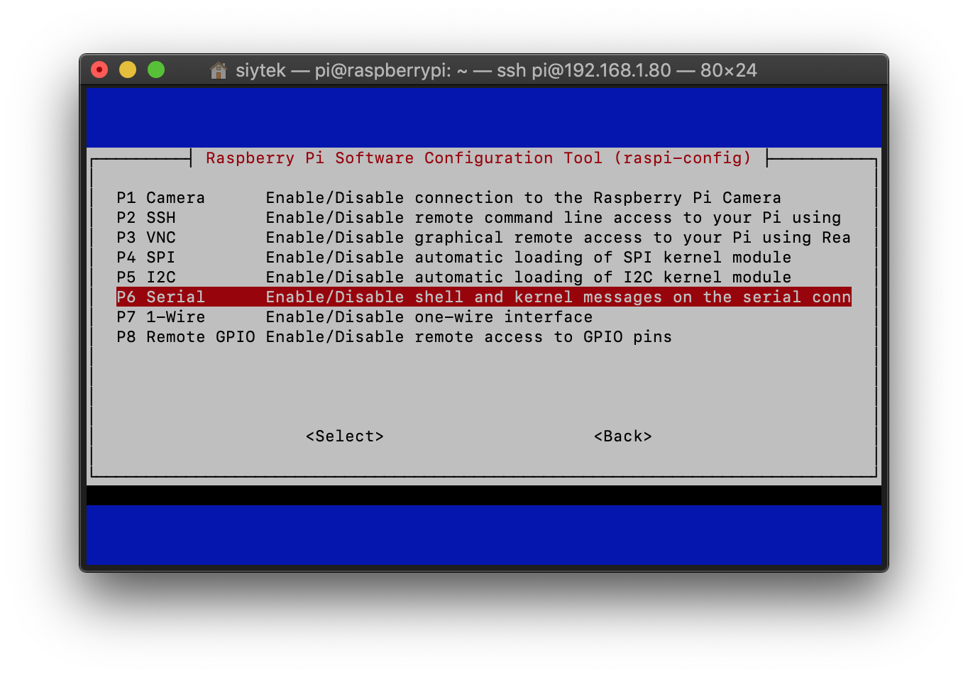
How To Configure Raspberry Pi for Serial Flashing
There are a few things that we need to do with the Pi configuration. By default the Pi is using the serial port in order to provide access to the terminal by serial connection. As we need the serial port for flashing, we must disable it.
We can disable this from the Pi config menu. Go ahead and enter the following command to bring up the settings menu.
sudo raspi-config
Next you will need to select interfacing options, followed by serial in the menus.
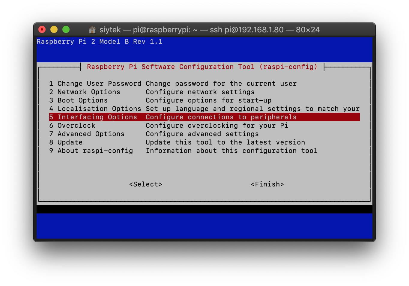
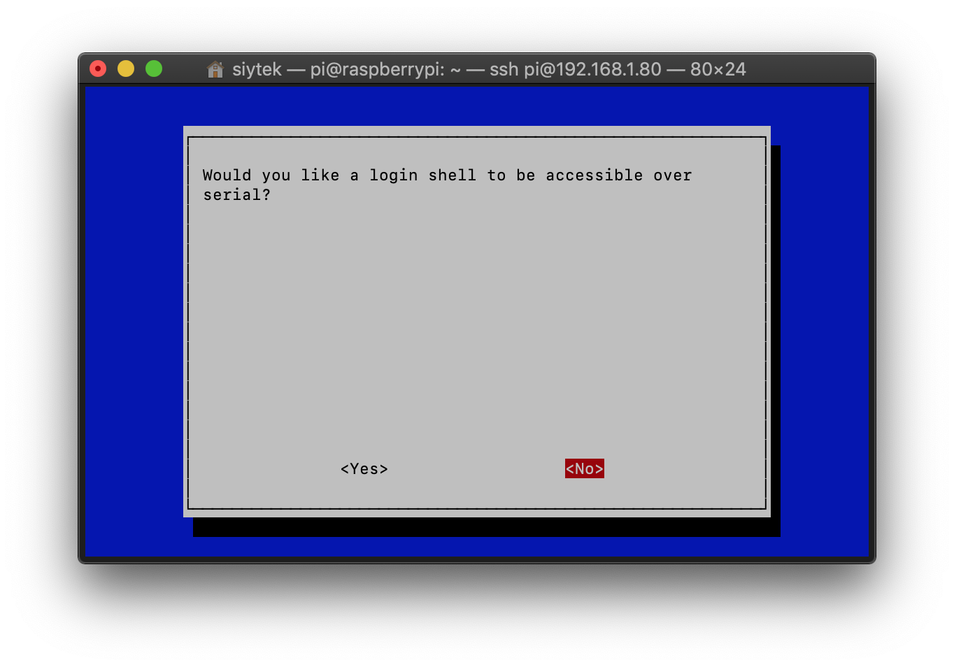
You will be presented with the option to disable the login shell being accessible over the serial port. Go ahead and select no.
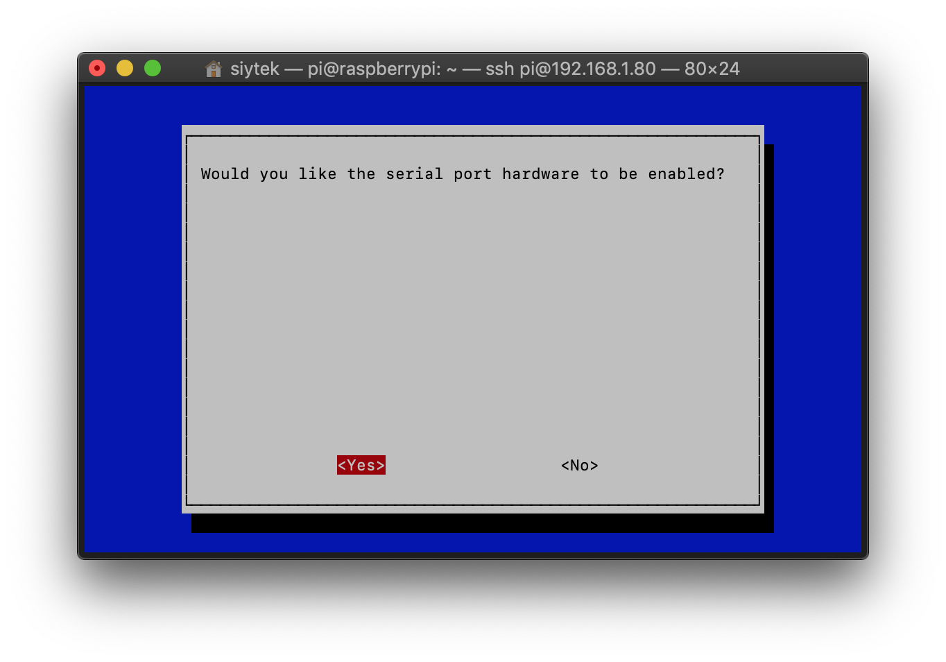
The next screen will ask if you would like serial hardware to be enabled. As we wish to use the serial port for flashing, go ahead and select yes.
The final screen will the confirm the options that you just selected. The configuration should be as follows.
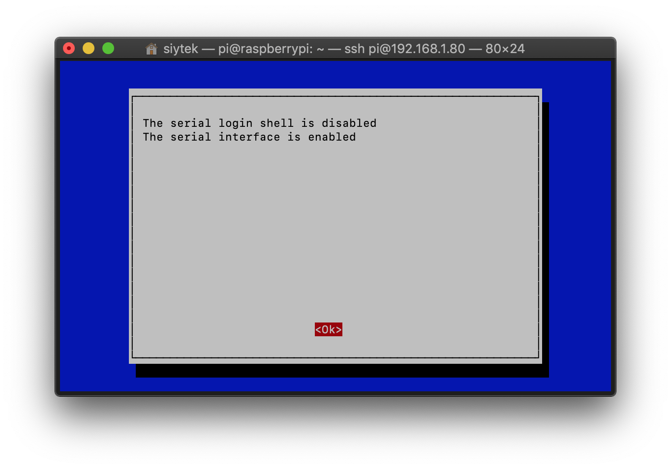
You will then be taken back to the main menu. Click finish and reboot your Pi. Now your Pi is configured for flashing and we can set up the hardware.
How to Wire Raspberry Pi for Serial Flashing
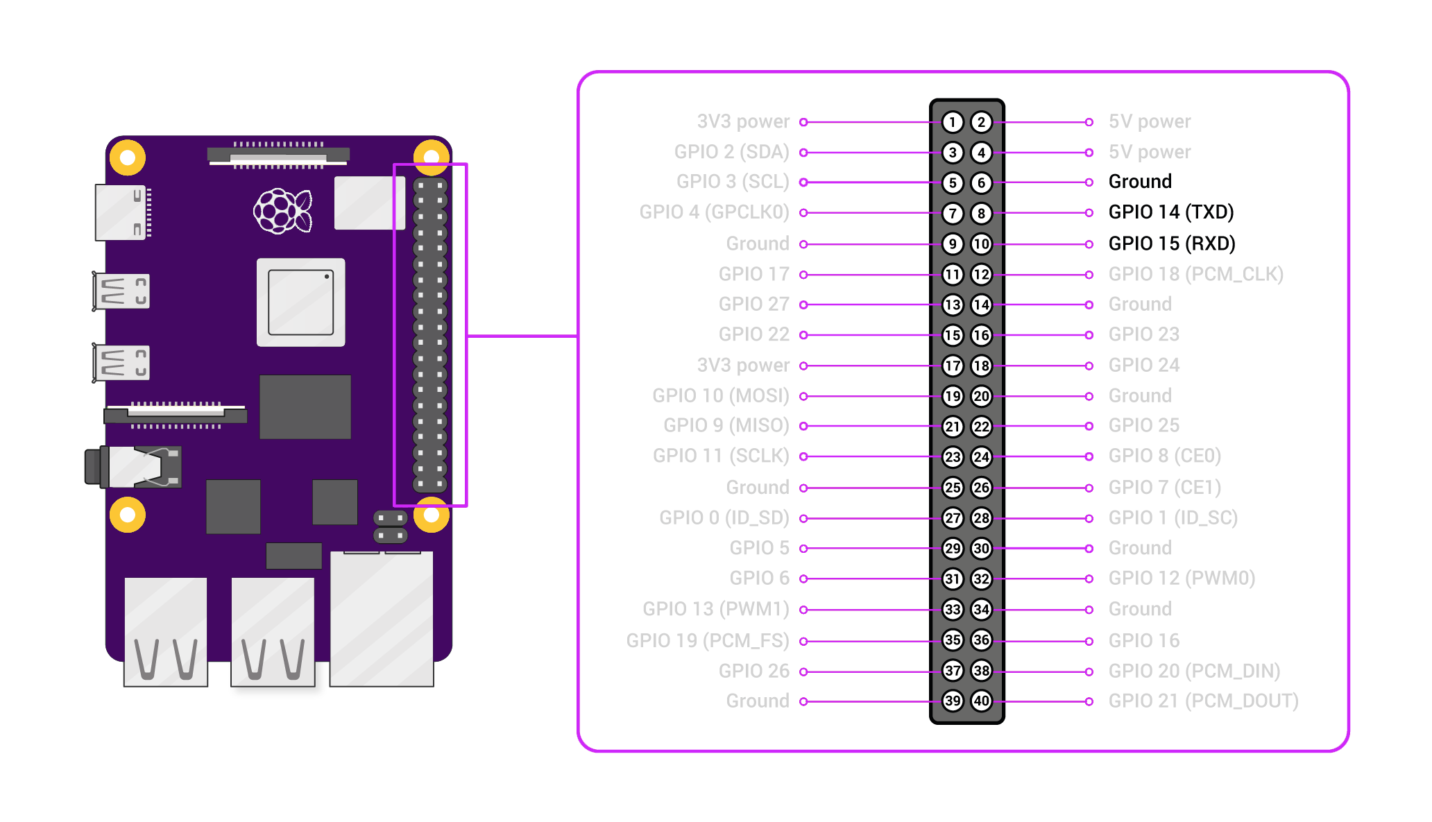
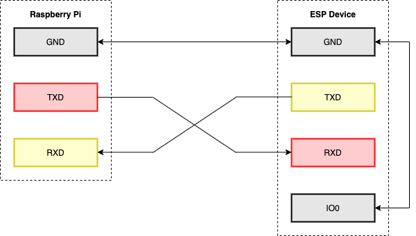
We need to connect our Pi to the device we wish to flash. The following diagram shows the pins that we are interested in on the GPIO header, TXD, RXD and Ground (GND).
They are conveniently located next to each other, so we can recycle an old RC servo lead to make the connection to the Pi header. Connections need to be made to pin 6, 8 and 10 as shown in the following diagram:
I would also highly recommend that you use an external power source for the device that you are flashing, so as not to cause problems or damage the Pi.
Disclaimer: drawing too much current from your Pi power pins can cause problems and could even damage your Pi.
Opening your device
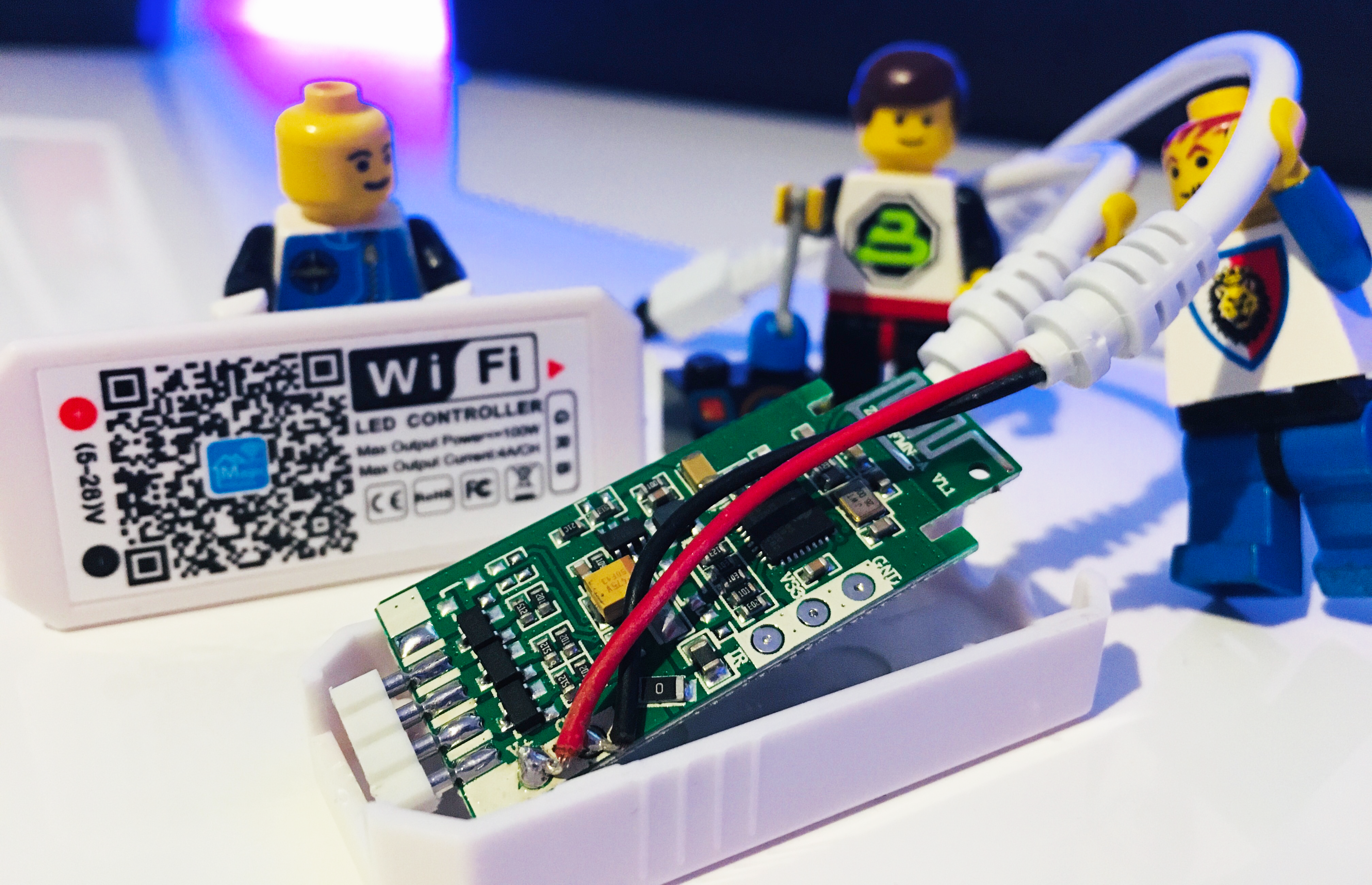
The device I am flashing is a MagicHome LED controller. I really like these devices as they are very cheap, easy to open up and they have labelled test points for all of the connections on the bottom of the circuit, which we can use to easily connect the wiring.
If you are flashing one of these MagicHome devices, simply pry the case open where the RGB connector is located. There are little clips on the side of the case that will pop open.
You can gently pry with a small flat-head screwdriver if needed. I have flashed a few of these devices and I didn’t break one of the clips yet! Once complete simply put the circuit back in the case and snap the lid back on.
It is also possible to flash these devices using their standard power supply adapter, we don’t need to use the power from the Pi.
This is device specific so you may need to search for the details of where to connect your device and how to power it. There will always be a TXD, RXD and GND somewhere on your ESP device, usually it will just be a case of locating the correct points to solder to.
I usually shop for devices that I know are easy to flash, rather than try to figure out if it is easy to flash something after I buy it. The Blakadder Templates Repository is usually a good place to start and everything here also has a corresponding Tasmota configuration template.
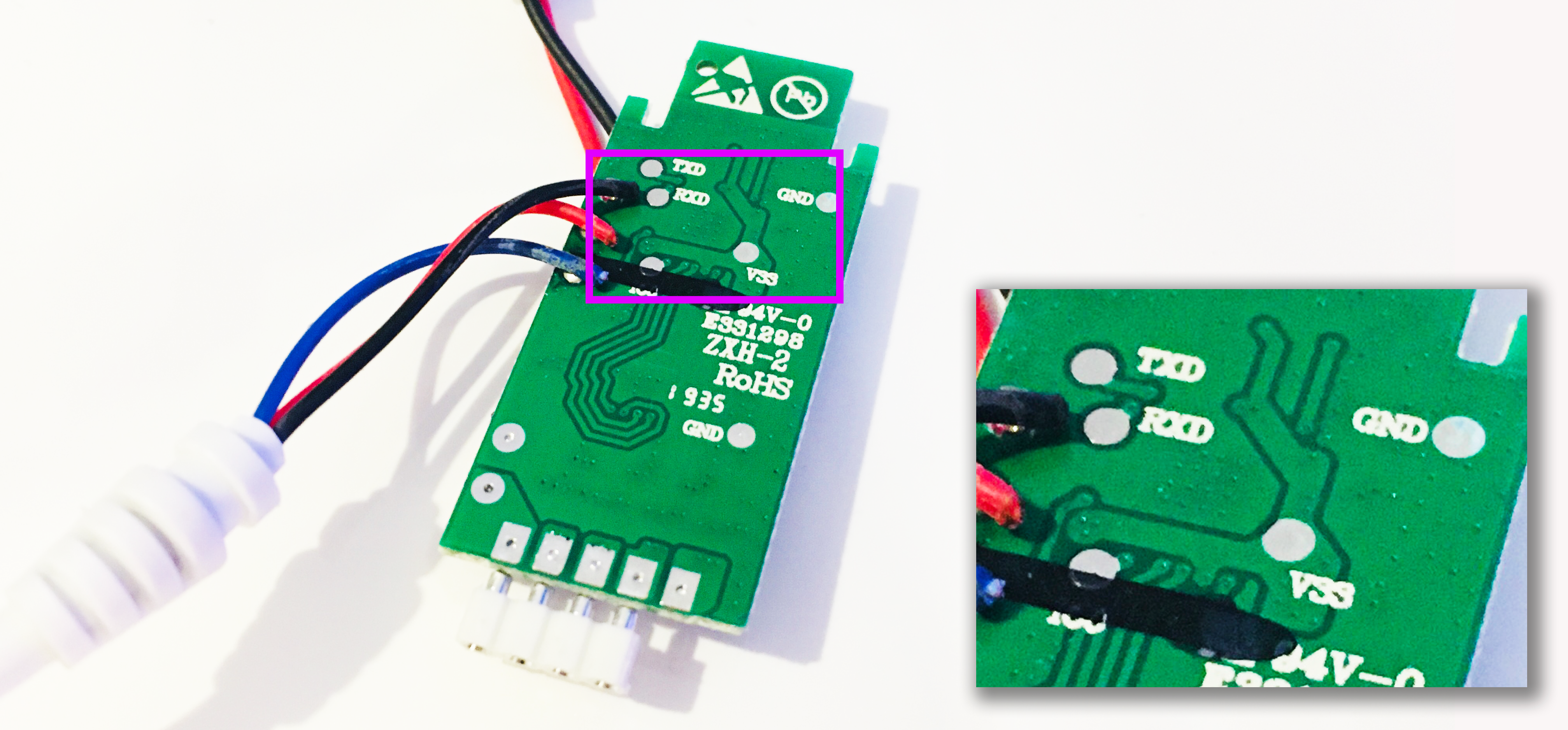
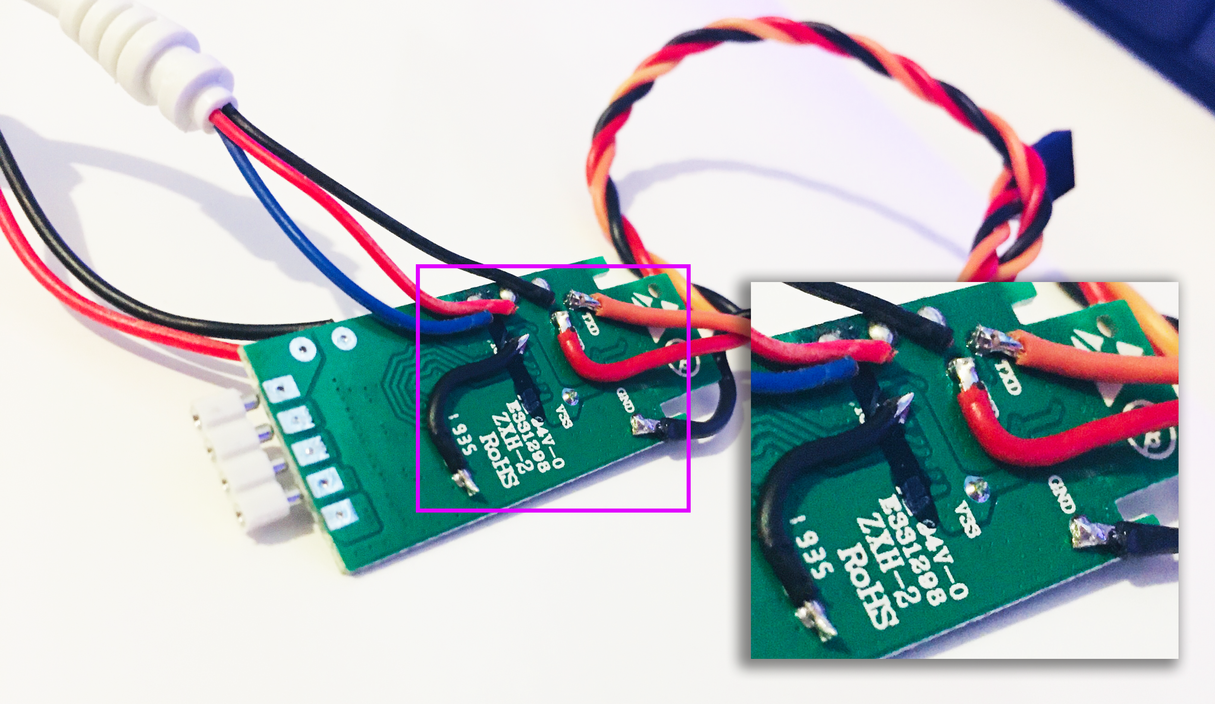
In my case the MagicHome device conveniently has the test points labelled. We need to connect TXD, RXD and GND to the Pi.
We also need to connect GPIO0 to GND in order to enabled flashing mode on the ESP chip. On these particular MagicHome devices this pin is labelled IO0 and in this case it is partially covered by a black line, although we should still be able to solder to it. We could probably remove it with some rubbing alcohol if necessary.
Required connections
The following block diagram should make it clear as to what needs to be connected where. I have omitted power as we will use the power adapter supplied with the device. Please note that it is important to still connect ground between the devices.
The easiest way to connect to the Pi header is to use an old RC servo lead, you can buy them or just cut one from an old RC servo if you have one lying around.
Alternatively you could solder directly to the Pi header, but I prefer this more elegant solution.
The end of the cable with the plug will connect to the Pi header. Cut, strip and solder tin the ends of the wires at the other end of the lead ready to solder to the device.
We will also need another short piece of wire, stripped and solder tinned at both ends to connect IO0 to GND.
Note that some devices have a button connected to GPIO0, you can use this instead if you like. You will need to press and hold it just before you run the ESPTool command.
Conveniently on these MagicHome devices there are two GND test points, therefore we can use one to connect to the Pi and one to connect IO0 to GND. If you do not have two GND pads available, just connect the Pi and IO0 to the same GND.
Soldering the wires
To solder on the wires, first make sure the ends of the wires are solder tinned and trim them to around 2mm in length. Then apply a little blob of solder to the test points. Now it should be nice and easy to neatly solder on the wires.
Note the little link lead connected between the extra GND pad and IO0, which puts the MagicHome device in to flashing mode. It is acceptable to solder this to the same GND as the Pi if you don’t have the extra GND point.
You MUST make sure you are absolutely certain that the wiring is correct, I always check three times. Remember, the first two pins on the header are +5V! Incorrect wiring could damage your device and/or your Pi, proceed at your own risk.
Now that the servo wire is attached to the device, we can connect it to our Pi. I have specifically used black for GND, therefore the black wire should connect to pin 6 of the Pi header (see the Pi pin out diagram).
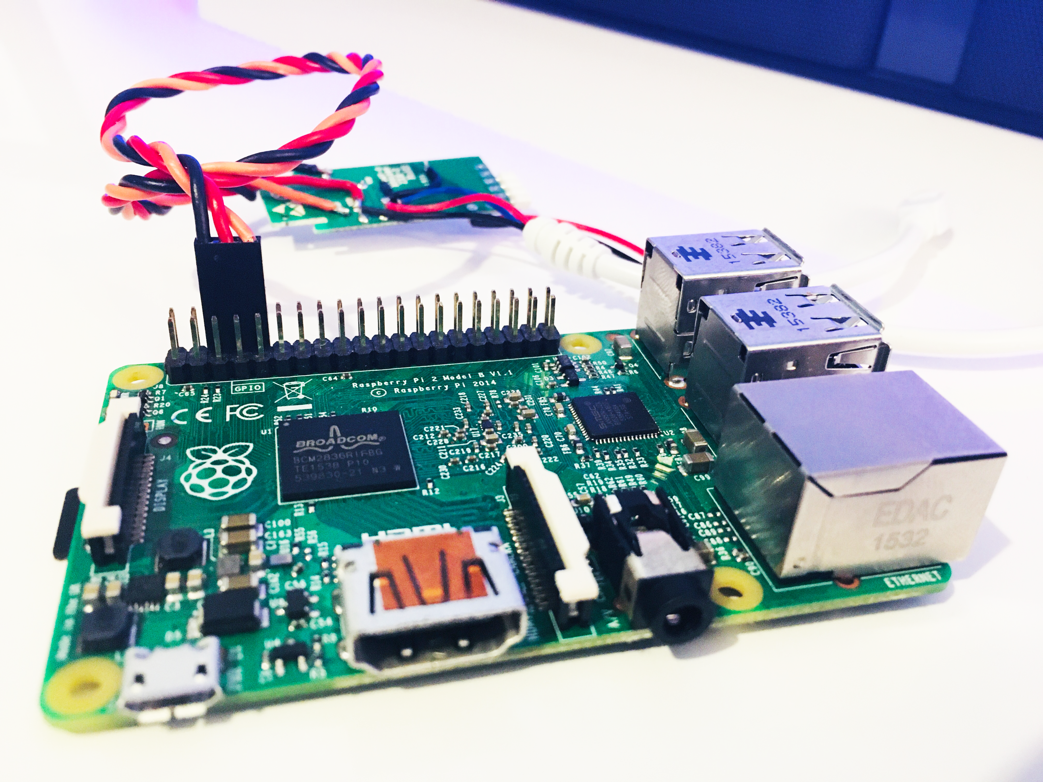
Congratulations! We have our hardware ready and now we can start to flash our device.
Flashing Tasmota using a Raspberry Pi Serial Port
Power up your Pi and bring up the terminal. If you did not connect your device to its power supply yet, go ahead and connect it.
Navigate to the folder where you installed ESPTool. Earlier in the tutorial I installed ESPTool to the ~/Documents folder but you should navigate to your chosen location from the earlier installation.
cd ~/Documents/esptool
Erase the flash
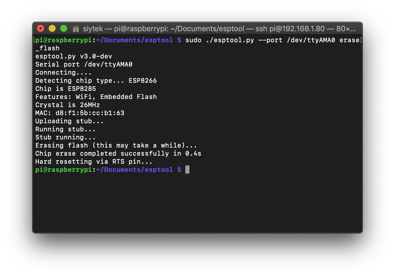
The first thing we should do is erase the flash memory to prevent any problems. The following command is used to erase the memory.
sudo ./esptool.py --port <your-device-port> erase_flash
We need to specify <your-device-port>, it is the port on the Pi that the ESP device is connected to.
If you are using a Pi 3 or 4 the port you need to use is /dev/ttyS0.
If you are using a Pi 2 then the port you need to use is /dev/ttyAMA0.
The reason for this is ttyAMA0 is the hardware serial port. On the Pi 2 this is connected directly to the GPIO pins. On the Pi 3 and 4 this is hard wired to the Bluetooth module and an additional serial port ttyS0 was added.
This is the port that connects to the GPIO on the newer Pi 3 and Pi 4 boards.
Now we can erase the flash memory. I would imagine that most folks are using the Pi 3 or 4 by now, therefore this would be the correct command.
sudo ./esptool.py --port /dev/ttyS0 erase_flash
I am using an old Pi 2 that I have lying around for flashing, therefore I will be entering the following command.
sudo ./esptool.py --port /dev/ttyAMA0 erase_flash
Upon successful completion you will receive confirmation from the script and your output should look something like the following.
Once complete you should disconnect your ESP device from the power supply and then reconnect it to reboot it.
Flash the firmware
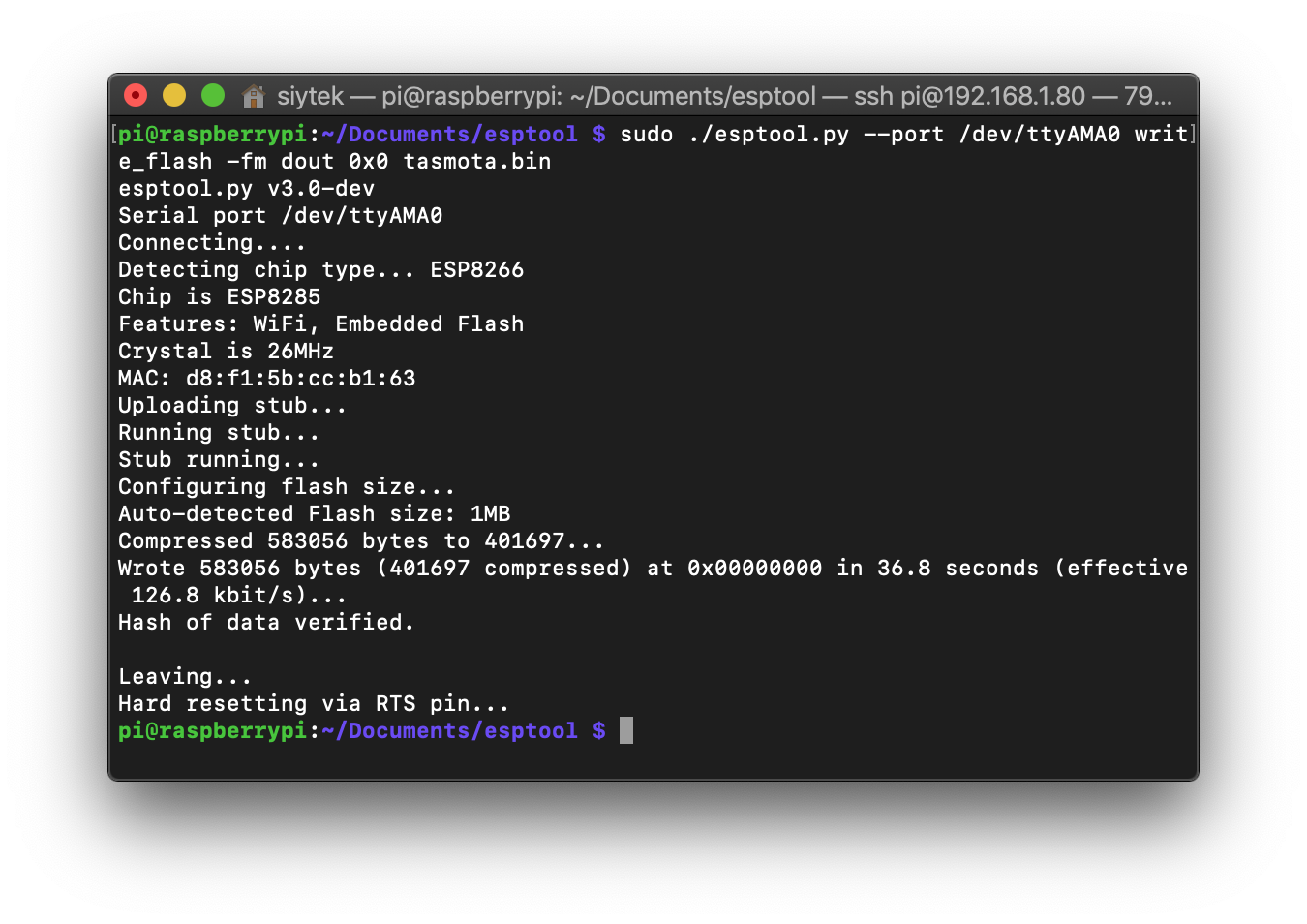
Now it is finally time to flash the firmware! In order to do so we will use the following command.
esptool.py --port <your-device-port> write_flash -fm dout -fs 0x0 <path-to-tasmota>.bin
As before you should use the correct port for your device. As I am using an old Pi 2, I shall be using port ttyAMA0. If you do not have your .bin file in the same directory as esptool.py, you should enter the full path to the .bin file.
I will use the following command to flash my device with the tasmota.bin file in the same directory.
sudo ./esptool.py --port /dev/ttyAMA0 write_flash -fm dout 0x0 tasmota.bin
If you are using a Pi 3 or Pi 4 then you will want to use /dev/ttyS0.
sudo ./esptool.py --port /dev/ttyS0 write_flash -fm dout 0x0 tasmota.bin
Flashing can take a minute and once complete, the script will confirm verification.
The last thing to do is disconnect your device from the Pi and the power supply and remove the servo lead/wiring that you added. Once you remove the link between IO0 and GND the device will boot as normal.
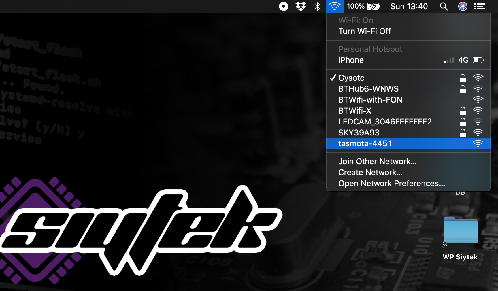
If you are using Tasmota, you should now see it appearing as an access point.
Conclusion
Congratulations on successfully flashing your ESP device using a Raspberry Pi! Now, it’s time to proceed with setting up Tasmota. To get started, refer to the comprehensive Tasmota setup guide for detailed instructions.
I’m glad this tutorial assisted you in successfully flashing your device. If you found it helpful, I invite you to explore more of my fantastic tutorials for further learning and guidance on various topics.
Article Updates
July 12th 2023 : Minor improvements to the wording and formatting, subheadings updated. Codemirror and TOC added. Featured image updated.
Article first published February 9th 2020.
Thanks so much for visiting my site! If this article helped you achieve your goal and you want to say thanks, you can now support my work by buying me a coffee. I promise I won't spend it on beer instead... 😏