It is possible to create a custom template for Tasmota for a device that does not exist in the template repository by simply taking a systematic approach to finding the correct GPIO functions.
In this tutorial we will learn about Tasmota templates and how they are structured. We will also go through the process of creating and using a template in Tasmota.
You will need a device that has been flashed with Tasmota and is connected to your WiFi network.
I have several detailed guides explaining how to flash Tasmota, I would recommend starting with how to use Tasmotizer if you are new to flashing Tasmota.
Table of Contents
Prerequisite
In order to understand the Tasmota template we should first understand some basics about what is happening under the hood.
Tasmota is designed to run on the Espressif Systems ESP8266 chip, a very common microcontroller with integrated WiFi.
One of the great things about this platform is that it is so widely used. The chip originates from China, therefore many Chinese devices are based on this chip.
There are some widely available devices using the ESP8266, such as the products that use the Tuya Smart Life app and the ubiquitous Wemos D1 Mini.
Tuya offer a fast track solution to companies wanting to get into the IoT domain, therefore mostly all brands offering the Smart Life app use the ESP8266 hardware.
Therefore if you are looking for devices to purchase that are Tasmota compatibile, Tuya products are a good bet. Personally I like the Lohas bulbs and use them throughout my home. However be mindful that not all devices are compatible with Tasmota.
So what does this mean? In simplistic terms it means there are a HUGE number of devices that are based on the ESP8266 chip and many of them are compatible with Tasmota.
ESP Pin functions
In order to better understand how the Tasmota template is composed, let’s take a look at the chip itself.
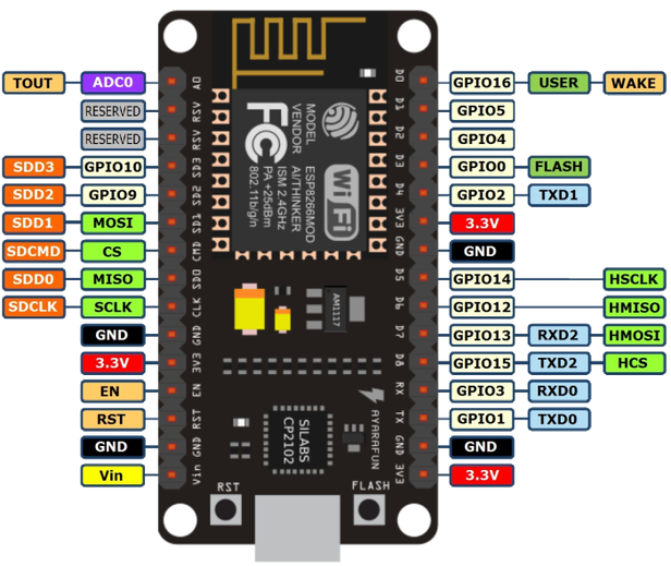
Wow! It certainly looks colourful! Don’t worry, it’s not as complicated as it first looks.
There are many flavours of ESP8266 module and this particular example features the ancillary electronics required for a complete WiFi system. It could be used in DIY projects, just add sensors, LEDs and power etc.
For the purpose of this tutorial we are only interested in the GPIO pins. These are the general purpose input output pins and can be assigned to different functions in Tasmota, known as components.
If we were to connect a switch to the pin GPIO1 we could assign the component Switch1 to this pin using a template. This tells Tasmota that there is a switch connected to GPIO1 and Tasmota will do all of the magic for us, so that this switch then appears in our smart home software.
So in summary we can say that Tasmota supports a large number of different devices that can be assigned to a series of GPIO pins on the ESP8266 chip.
Anatomy of a template
So now that we understand a little about what is going on under the hood, lets go through the process of using a template in Tasmota.
If you have flashed devices with Tasmota before, you may have used the configure other menu to input a template already. I will briefly cover it for those that are new to Tasmota.
Firstly we need to start with a premade template for our device. The Blakadder template repository is a great place to locate a template for an existing device that is not already listed in the module configuration.
Recently I flashed Tasmota on to a Lohas ZN033 so I will use the premade template for this device as an example.
{"NAME":"Lohas RGBWW","GPIO":[0,0,0,0,38,37,0,0,41,39,40,0,0],"FLAG":0,"BASE":18}
We can break this template up into four sections. Each section in the template is separated by a comma.
Name
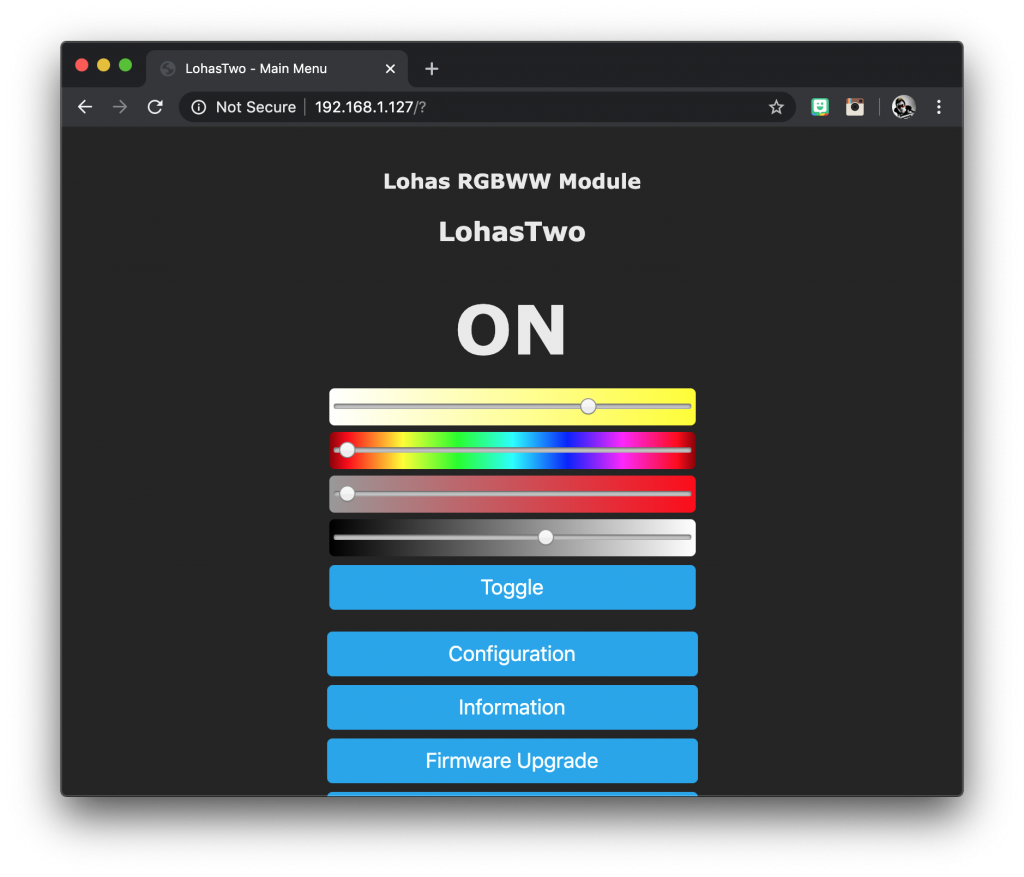
The name is fairly self explanatory, it is the name of the template. This name will appear at the top of the main menu as <template name> module.
GPIO
This is the string of available GPIO pins separated by commas, they represent GPIO0, 1, 2, 3, 4, 5, 9, 10, 12, 13, 14, 15 and 16 respectively.
Note that GPIO6, 7, 8, 11 are reserved for other functions and are unavailable.
Remember that the actual value of the number represents the component and the position within the string represents the GPIO pin.
If you look at our example for the Lohas bulb, component “38” is assigned to GPIO4. You can see a full list of the components in the Tasmota documentation.
Flag
The flag is used to configure the analog to digital convertor, or ADC. In most cases it won’t be required.
Discussing the ADC is beyond the scope of this tutorial, but you can read more about it in the Tasmota documentation.
Base
Tasmota has an extensive library of modules supported out of the box. Some of them have special features, therefore it is important to choose the module correctly in these cases.
You can base your template on an existing module and it would be advised if you are trying to make a template for a similar device.
However you can start with a blank canvas by choosing the generic (18) module.
It is also worth noting that modules, like peripherals, are denoted with a number in brackets after the name. In order to reference the module in the template, you should use the corresponding numbers. You can find a complete list in the Tasmota documentation.
Adding a template to Tasmota
Tasmota provides us with a text box to enter the template. We can simply cut and paste it from a template repository or notepad, or just edit it within the text box.
From the main menu, click configuration and then configuration other. This will take you to the menu where you can enter your template.
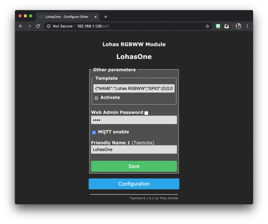
Simply enter the template into the template text box and make sure the tick box activate is ticked.
You can enter a friendly name here too if you like. This is the name that will appear in Home Assistant. Check out this tutorial on how to set up MQTT in Tasmota for further information.
Making a template
Now that we understand how sensors and other peripherals are connected to the chip and we understand how a template is structured, we can just go ahead and write a template!
No idea where to start because you don’t know what the GPIOs in your device are connected to?
Sometimes it is a case of trial and error, you can read about the process here in my post about converting a smart lamp.
If you are starting out with a smart bulb and you don’t know which GPIO is connect to which LED, start by setting all of the GPIOs to component ‘0’ so that Tasmota sets them to ‘not used’. Then change each one to component ’37’ sequentially, starting with GPIO0.
Each time you make a change to the template, click save and allow Tasmota to reboot. As we are only setting the PWM1 component (a dimmable LED output), Tasmota will configure itself as a single colour LED light.
Test the brightness and if you stumble upon a GPIO pin that is connected to an LED, you will see it spring into action! Make a note of the GPIO pin and the colour.
Rinse and repeat until you have found all of the LEDs, then you can create your complete template. For further reading on this process, go check out my article here.
I hope that you found this article useful! Please take a moment to go check out some of my other cool Home Assistant tutorials!
Thanks so much for visiting my site! If this article helped you achieve your goal and you want to say thanks, you can now support my work by buying me a coffee. I promise I won't spend it on beer instead... 😏