In the ever-expanding landscape of the Internet of Things (IoT), the ESP8266 has emerged as a versatile and powerful platform, enabling developers and hobbyists to effortlessly connect their devices to the digital realm.
With its built-in WiFi capabilities and low-cost design, the ESP8266 has become a go-to choice for numerous IoT projects. One particularly useful feature of this tiny but mighty microcontroller is its ability to function as a WiFi access point.
In this article, we delve into the process of setting up an ESP8266 as a WiFi access point (AP), allowing you to establish a standalone network that devices can connect to.
Whether you’re looking to create a local network for data transfer, develop a smart home system, or simply experiment with wireless communication, understanding how to harness the potential of the ESP8266 as a WiFi access point is an invaluable skill.
By the end of this article, you will possess the knowledge and expertise needed to unlock the full potential of the ESP8266 as a WiFi access point. So let’s dive in and embark on an exciting journey of connectivity and innovation with this remarkable microcontroller.
Prerequisite
Before diving into the process of setting up the ESP8266 as a WiFi access point, it is important to ensure that you have the following prerequisites in place:
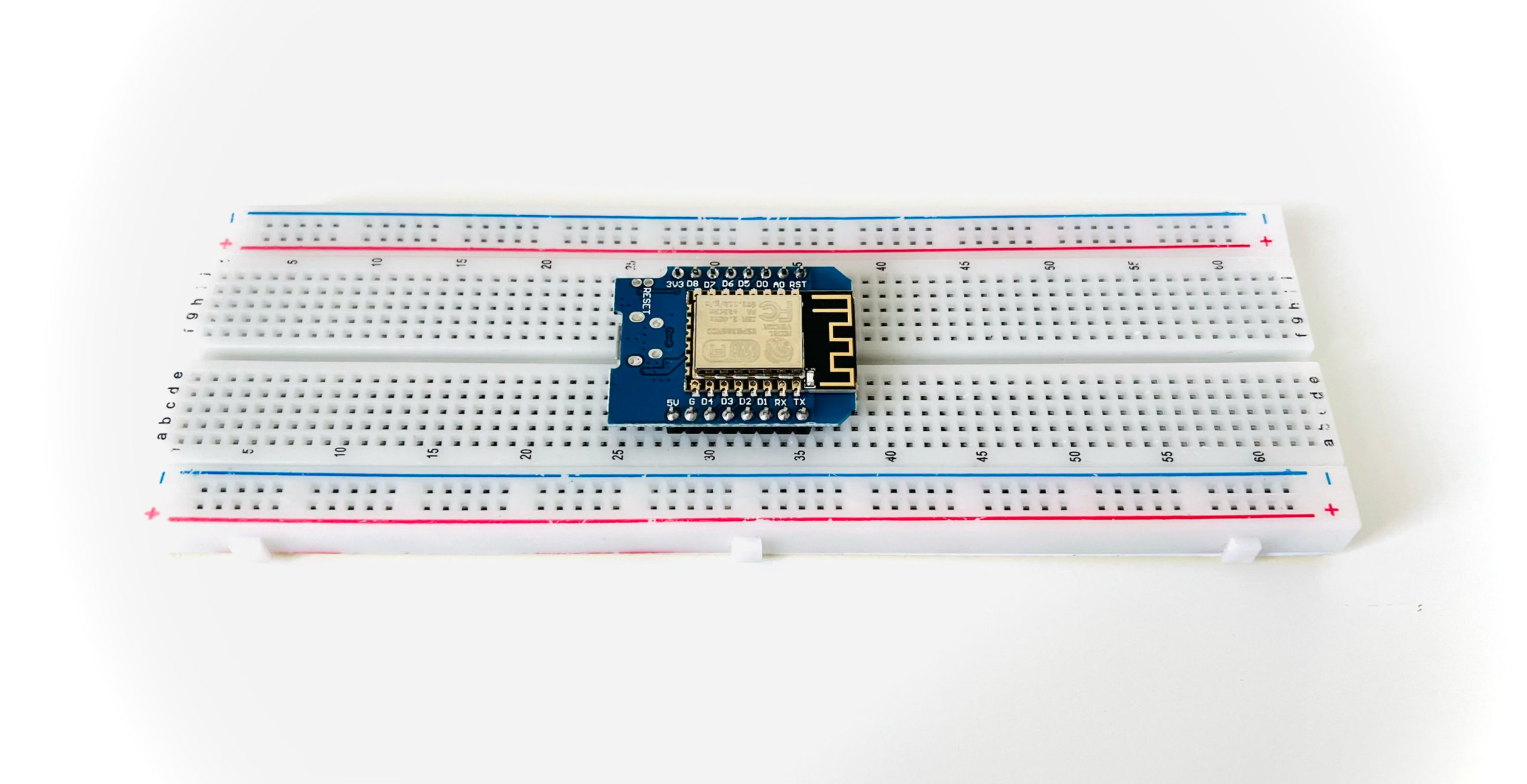
- ESP8266 Development Board: Acquire an ESP8266 development board, such as the popular Wemos D1 Mini. These boards provide a convenient platform for programming and testing your ESP8266 projects.
- Arduino IDE: Install the Arduino Integrated Development Environment (IDE) on your computer. The Arduino IDE is widely used for programming ESP8266 boards and provides a user-friendly interface for writing and uploading code.
- USB Cable: Prepare a USB cable that can connect your ESP8266 development board to your computer. This cable is essential for powering the board and uploading code.
Introduction to ESP8266 and its WiFi Capabilities
The ESP8266 has rapidly gained popularity as a versatile and cost-effective microcontroller with built-in WiFi capabilities, revolutionizing the world of Internet of Things (IoT) development.
The ESP8266 is a low-cost, highly integrated system-on-a-chip (SoC) microcontroller developed by Espressif. Despite its compact size, the ESP8266 packs a punch with its processing power and most notably, it’s onboard WiFi capabilities.
The ESP8266 combines a microcontroller unit (MCU) based on the Tensilica Xtensa Diamond Standard architecture, RAM, flash memory, and a WiFi module, all on a single chip.
WiFi Capabilities of the ESP8266
The standout feature of the ESP8266 is its integrated WiFi functionality, which allows devices to connect to wireless networks and communicate with other devices or the internet. Here are some key WiFi capabilities of the ESP8266:
- WiFi Standards and Protocols: The ESP8266 supports popular WiFi standards, including 802.11 b/g/n, allowing it to communicate with a wide range of WiFi-enabled devices. It also supports various security protocols such as WPA, WPA2, and WEP for secure wireless communication.
- Access Point and Station Modes: The ESP8266 can operate in two main modes: access point (AP) mode and station (STA) mode. In AP mode, it can act as a standalone WiFi access point, allowing other devices to connect to it. In STA mode, it can connect to an existing WiFi network as a client, enabling it to access the internet or communicate with other devices on the network.
- TCP/IP Stack: The ESP8266 includes a robust TCP/IP protocol stack, enabling seamless communication over the internet or local network. It supports protocols such as HTTP, MQTT, and WebSocket, making it suitable for a wide range of IoT applications.
- Web Server and Web Client: The ESP8266 can function as a web server, serving web pages or APIs to connected devices. Additionally, it can act as a web client, allowing it to send HTTP requests to remote servers and retrieve data.
- Low Power Consumption: The ESP8266 is designed to be power-efficient, making it suitable for battery-powered or energy-conscious IoT projects. It offers various sleep modes and power-saving features, allowing developers to optimize power consumption based on their application requirements.
The ESP8266 as a WiFi Access Point
By leveraging the ESP8266’s WiFi capabilities, you can set it up as a standalone WiFi access point, creating a local network for devices to connect to.
This opens up a world of possibilities, from building IoT projects that require direct device-to-device communication to creating custom wireless networks for specific applications.
Understanding WiFi Access Points
In the world of wireless networking, WiFi access points play a crucial role in providing connectivity and enabling devices to communicate with each other.
What is a WiFi Access Point?
A WiFi access point, often referred to as an AP, is a device that creates a wireless local area network (WLAN) by transmitting and receiving data to and from connected devices.
It serves as a central hub for communication, allowing wireless devices such as smartphones, laptops, and IoT devices to connect to a network and access resources like the internet or other devices on the network.
Unlike routers, which are responsible for routing network traffic between different networks (such as between your home network and the internet), access points are primarily concerned with providing wireless connectivity within a single network.
Features and Functionality
WiFi access points offer several key features and functionalities that make them essential components of modern wireless networks. Here are some important aspects to understand:
- Wireless Connectivity: Access points transmit and receive wireless signals using specific frequencies and protocols, such as 2.4 GHz or 5 GHz bands. They enable devices to connect to the network wirelessly, eliminating the need for physical cables.
- Network Identification: Each access point has a unique identifier called a Service Set Identifier (SSID). The SSID represents the network name that devices use to identify and connect to a specific access point.
- Security: Access points provide security measures to protect the network and connected devices from unauthorized access. Encryption protocols, such as WPA2 (Wi-Fi Protected Access II), help secure data transmission over the wireless network.
- Multiple Connections: Access points can handle multiple client connections simultaneously, allowing numerous devices to connect and communicate within the network.
Access Point vs. Router
While access points and routers both play vital roles in networking, it is important to understand their differences:
- A router connects different networks and directs network traffic between them, such as your home network and the internet. It typically includes features like network address translation (NAT) and firewall capabilities.
- An access point focuses on wireless connectivity within a single network. It provides wireless access to devices and is often connected to a router to enable internet access.
It is worth noting that many modern routers combine the functionalities of a router and an access point into a single device, simplifying network setup and management.
Setting Up the Arduino IDE for ESP8266 Development
To begin the setup process, it is essential to have the latest version of the Arduino IDE installed on your computer. We will also need to add the necessary ESP8266 packages to the Arduino IDE.
Installing the Latest Version of Arduino IDE
If you do not already have the Arduino IDE, simply download and install the latest version from the official website.
Linux users may find additional information and instructions on the Arduino website, specifically tailored to their operating system. This resource can provide helpful guidance to ensure a smooth installation process.
Adding the ESP8266 To Arduino using the Board Manager
The Arduino Board Manager is a feature within the Arduino IDE that allows users to easily add support for various microcontroller boards by installing the necessary board definitions and libraries.
It simplifies the process of programming and uploading code to different boards, providing a streamlined experience for developers.
In order to program ESP8266 using Arduino, we will need to use the board manager to add the ESP8266 boards.
- Open the Arduino IDE and click Settings.
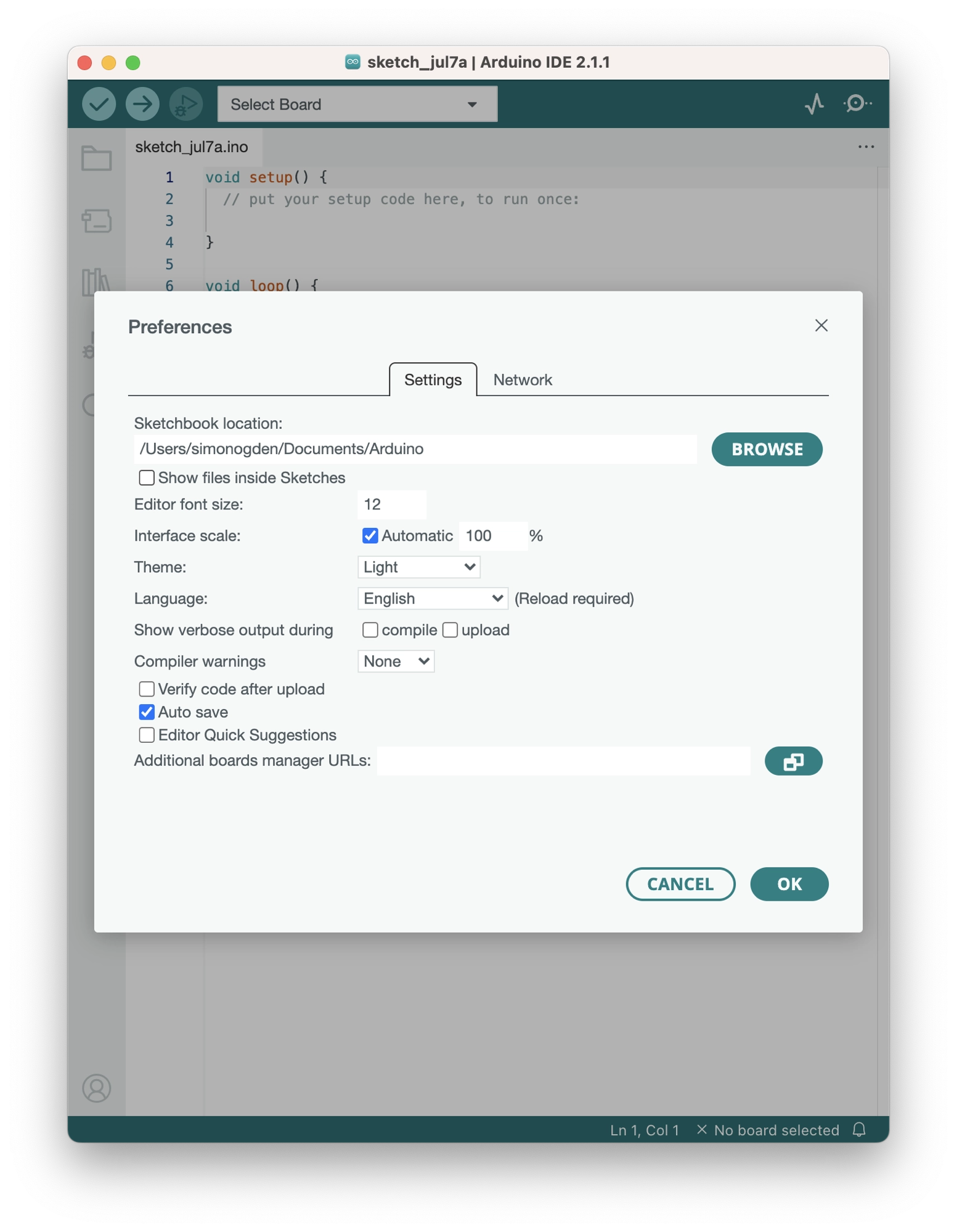
- Enter the following URL into the additional board manager URLs text box. If you need to use multiple board managers, you can click the small icon to the right of the text box and enter multiple URLs.
https://arduino.esp8266.com/stable/package_esp8266com_index.json
- Click OK.
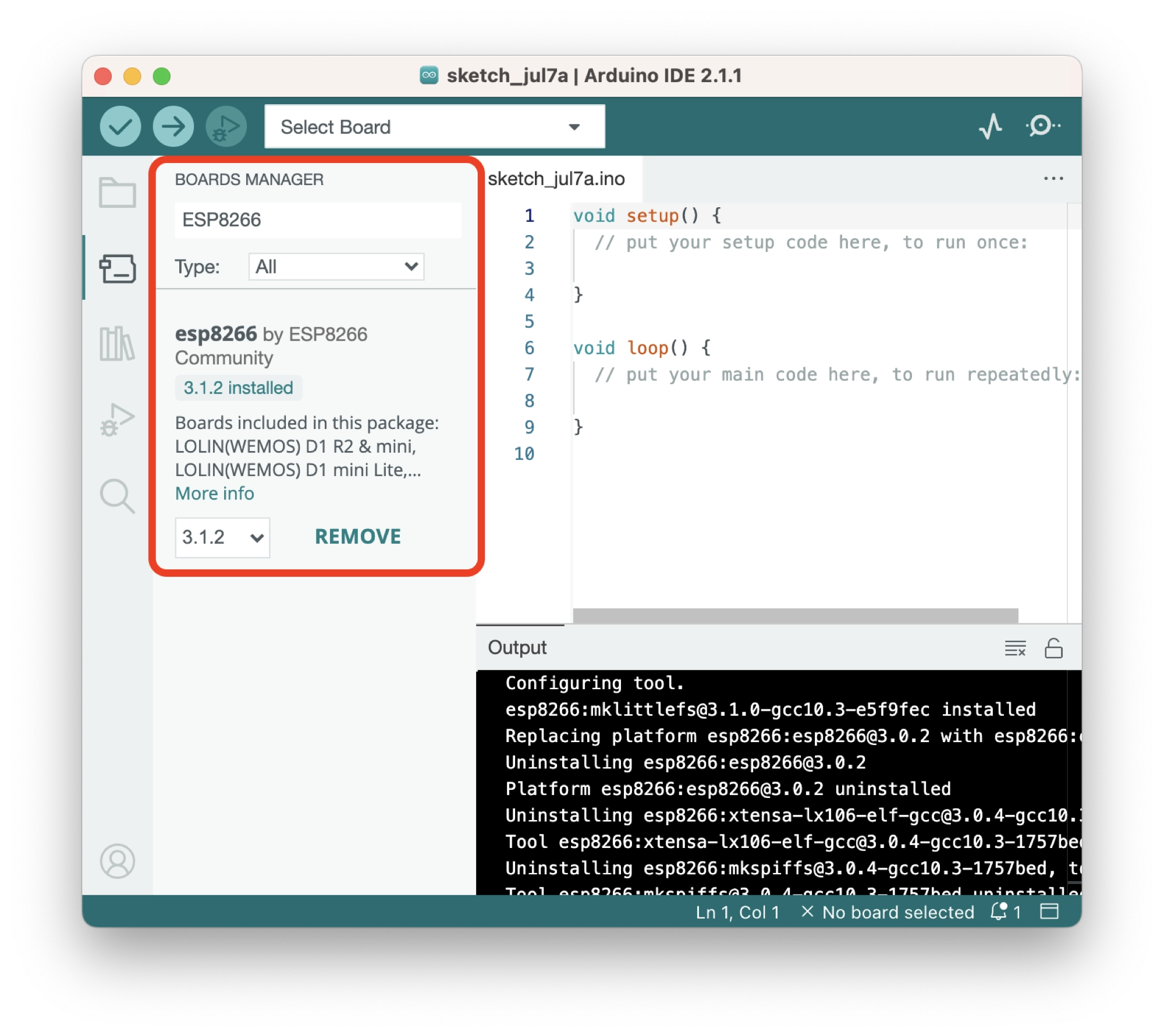
Adding ESP8266 Boards to Arduino
Now we can add the ESP8266 boards by clicking the tools > board > boards manager… option on the menu. Search for the ESP8266 library and install it.
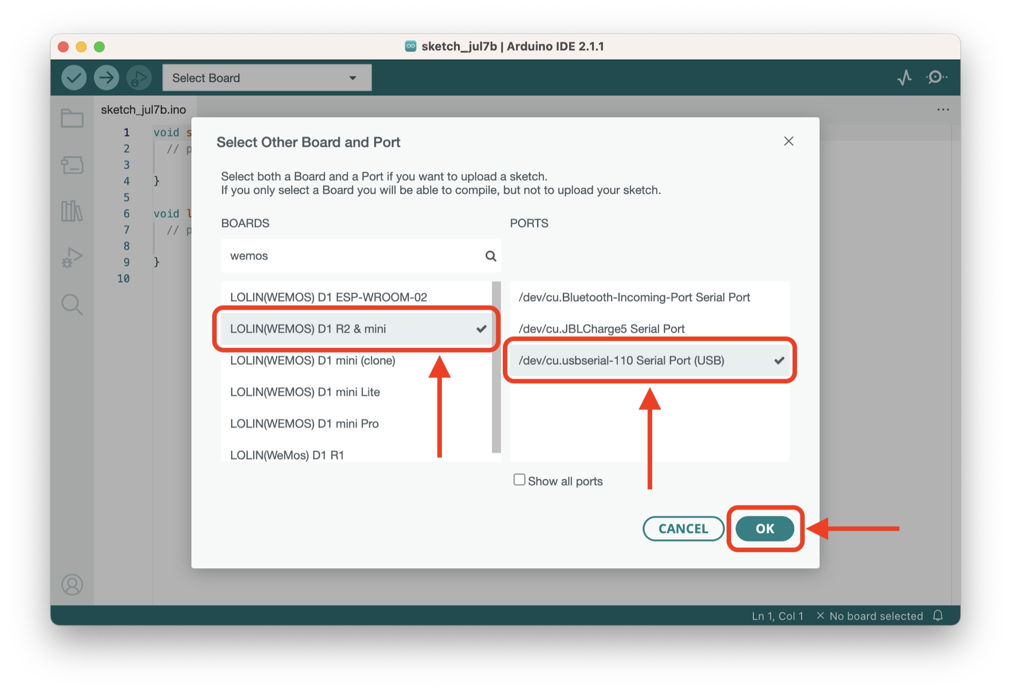
How to Connect Arduino to an ESP8266 Board and Port
Once the ESP8266 boards library has been installed, we can connect to the ESP8266:
- Connect the ESP8266 to the computer using a USB cable.
- Click the Select Board… drop down menu and select your board:
- Mac/Linux users: the port will be something similar to
/dev/tty.usbserial - Windows users: the port will be something similar to
COM6
- Mac/Linux users: the port will be something similar to
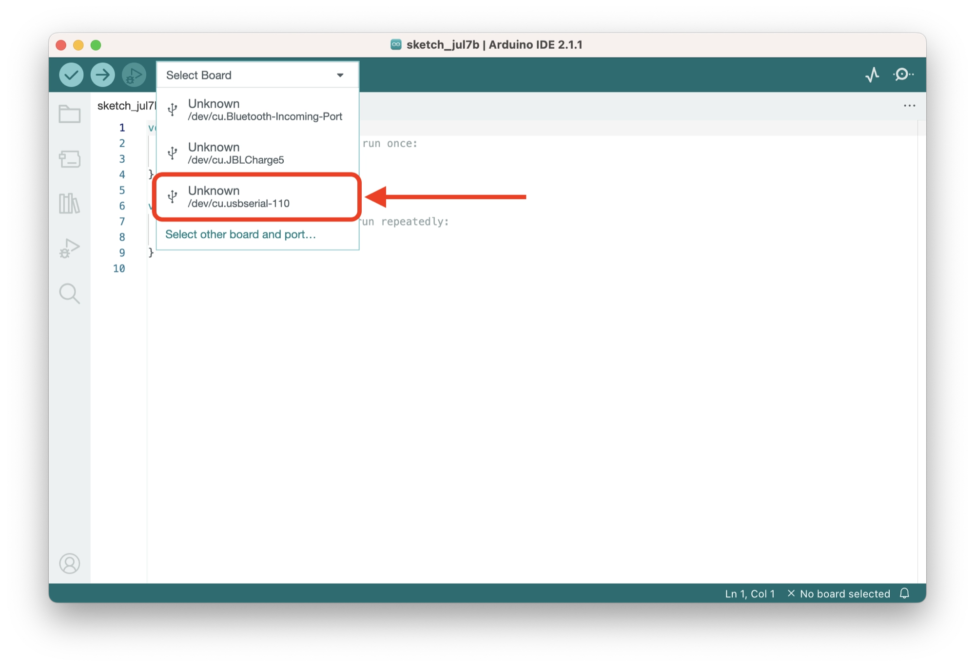
- Choose your ESP8266 in the left-hand column. In this example we are using the Wemos D1 Mini.
- Click OK.
Writing the Access Point Code
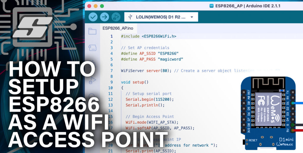
For our access point example we will use the following code in a new Arduino project in order to create an access point:
#include <ESP8266WiFi.h>

// Set AP credentials
#define AP_SSID "ESP8266"
#define AP_PASS "magicword"

void setup()
{
  // Setup serial port
  Serial.begin(115200);
  Serial.println();

  // Begin Access Point
  WiFi.mode(WIFI_AP);
  WiFi.softAP(AP_SSID, AP_PASS);

  // Print access point IP
  Serial.print("IP address for network ");
  Serial.print(AP_SSID);
  Serial.print(" : ");
  Serial.print(WiFi.softAPIP());

}

void loop() {
  // put your main code here, to run repeatedly:

}
Let’s take a look at what each section of this code is doing:
#include <ESP8266WiFi.h>
This line includes the ESP8266WiFi library, which provides functions to connect to and manage Wi-Fi networks using the ESP8266 module.
// Set AP credentials
#define AP_SSID "ESP8266"
#define AP_PASS "magicword"
These lines define two constants: AP_SSID is set to “ESP8266” and AP_PASS is set to “magicword”. These constants represent the desired SSID (network name) and password for the access point.
void setup()
{
  // Setup serial port
  Serial.begin(115200);
  Serial.println();

  // Begin Access Point
  WiFi.mode(WIFI_AP_STA);
  WiFi.softAP(AP_SSID, AP_PASS);

  // Print access point IP
  Serial.print("IP address for network ");
  Serial.print(AP_SSID);
  Serial.print(" : ");
  Serial.print(WiFi.softAPIP());
}
This section defines the setup function. The setup function is a special function that is executed once when the microcontroller (ESP8266) starts up.
Inside the setup function:
Serial.begin(115200);initializes the serial communication at a baud rate of 115200 bits per second.Serial.println();sends an empty line to the serial port, which helps separate the output for readability.WiFi.mode(WIFI_AP);sets the ESP8266’s Wi-Fi mode to access point (AP).WiFi.softAP(AP_SSID, AP_PASS);starts an access point with the provided SSID and password.Serial.print("IP address for network ");sends the text “IP address for network ” to the serial port.Serial.print(AP_SSID);sends the value ofAP_SSID(which is “ESP8266”) to the serial port.Serial.print(" : ");sends the text ” : ” to the serial port.Serial.print(WiFi.softAPIP());retrieves the IP address of the access point and sends it to the serial port.
void loop() {
  // put your main code here, to run repeatedly:
}
This section defines the loop function. The loop function is a special function that is executed repeatedly after the setup function.
In our example, the loop function is empty, indicated by the comment // put your main code here, to run repeatedly:. It means that there is no specific code to execute in an infinite loop.
This is the section where you can start to build your ESP8266 project, leveraging your new WiFi access point.
Handling Client Connections With a Web Server
Now that we have the basic code in place and the access point is live, let’s take a look at a simple example of handling the client connections.
We can do this using the ESP8266 web server, which is bundled in the ESP8266 library. The following code gives a simple example whereby a client request is handled:
#include <ESP8266WiFi.h>

// Set AP credentials
#define AP_SSID "ESP8266"
#define AP_PASS "magicword"

WiFiServer server(80); // Create a server object listening on port 80

void setup()
{
  // Setup serial port
  Serial.begin(115200);
  Serial.println();

  // Begin Access Point
  WiFi.mode(WIFI_AP_STA);
  WiFi.softAP(AP_SSID, AP_PASS);

  // Print access point IP
  Serial.print("IP address for network ");
  Serial.print(AP_SSID);
  Serial.print(" : ");
  Serial.print(WiFi.softAPIP());

  server.begin(); // Start the server
  Serial.println("\nServer started");
}

void loop()
{
  WiFiClient client = server.available(); // Check if a client has connected

  if (client)
  {
    Serial.println("New client connected");
    while (client.connected())
    {
      if (client.available())
      {
        String request = client.readStringUntil('\r'); // Read the client's request until a carriage return is received
        Serial.print("Client request: ");
        Serial.println(request);

        // Send a response to the client
        client.println("HTTP/1.1 200 OK");
        client.println("Content-Type: text/html");
        client.println("");
        client.println("<html><body><h1>Hello, client!</h1></body></html>");
        break; // Exit the loop after sending the response
      }
    }
    delay(100); // Small delay to allow the client to process the response
    client.stop(); // Disconnect the client
    Serial.println("Client disconnected");
  }
}
Let’s go through the code changes step by step:
The program includes the necessary library (ESP8266WiFi.h) to work with the ESP8266 module.
#include <ESP8266WiFi.h>
Constants are defined for the access point (AP) credentials: SSID (network name) and password.
#define AP_SSID "ESP8266"
#define AP_PASS "magicword"
A server object is created to listen for incoming connections on port 80.
WiFiServer server(80);
The setup function is called, which runs once when the microcontroller starts up.
void setup()
{
  Serial.begin(115200);
  Serial.println();

  WiFi.mode(WIFI_AP_STA);
  WiFi.softAP(AP_SSID, AP_PASS);

  Serial.print("IP address for network ");
  Serial.print(AP_SSID);
  Serial.print(" : ");
  Serial.print(WiFi.softAPIP());

  server.begin();
  Serial.println("\nServer started");
}- The serial port is initialized for communication with the computer.
- The ESP8266 is configured to operate in both access point (AP) and station (STA) mode.
- The access point is started with the specified SSID and password.
- The IP address of the access point is printed to the serial port.
- The server is started on port 80, and a message is printed to indicate that the server has started.
Next, the loop function is called, which runs repeatedly after the setup function.
void loop()
{
  WiFiClient client = server.available();

  if (client)
  {
    Serial.println("New client connected");
    while (client.connected())
    {
      if (client.available())
      {
        String request = client.readStringUntil('\r');
        Serial.print("Client request: ");
        Serial.println(request);

        client.println("HTTP/1.1 200 OK");
        client.println("Content-Type: text/html");
        client.println("");
        client.println("<html><body><h1>Hello, client!</h1></body></html>");
        break;
      }
    }
    delay(100);
    client.stop();
    Serial.println("Client disconnected");
  }
}- The code checks if a client has connected to the server.
- If a client is connected:
- A message is printed to the serial port indicating that a new client has connected.
- The code enters a loop that continuously checks for data from the client.
- If data is available from the client:
- The client’s request is read until a carriage return character is received.
- The client is sent a simple HTTP response with an HTML message.
- The loop is exited after sending the response.
- A small delay is added to allow the client to process the response.
- The client is disconnected.
- A message is printed to the serial port indicating that the client has disconnected.
That’s it! With these modifications, the code will handle incoming client connections, read their requests, and send a simple response back to them.
Troubleshooting and Common Issues
Here are some common troubleshooting issues you may encounter when working with Wi-Fi and the ESP8266 module, along with their possible solutions:
Connection issues
- Issue: The ESP8266 is not connecting to the desired Wi-Fi network or the access point is not visible.
- Solution:
- Double-check the SSID and password in the code to ensure they are correct.
- Verify that the Wi-Fi network is within range and functioning properly.
- Make sure there are no special characters or spaces in the SSID or password.
- Try restarting both the ESP8266 and the Wi-Fi router/access point.
- Check for any MAC address filtering or other security settings on the router that may be preventing the connection.
Serial communication issues
- Issue: The serial output is not visible or not showing the expected information.
- Solution:
- Ensure that the correct baud rate is set in the
Serial.begin()function. It should match the baud rate configured in the serial monitor of the Arduino IDE or the terminal software you are using. - Verify that the ESP8266 is properly connected to the computer via the appropriate serial communication pins (usually RX and TX).
- Make sure the serial monitor or terminal software is configured correctly to receive data from the ESP8266.
- Ensure that the correct baud rate is set in the
Client connection issues
- Issue: The client connection is not established or the server is not receiving any data from the client.
- Solution:
- Check that the client device (e.g., web browser) is connected to the same network as the ESP8266 access point.
- Verify that the client is attempting to connect to the correct IP address and port specified in the code.
- Ensure that the client request and response protocols (e.g., HTTP) are compatible and correctly implemented on both ends.
- Confirm that there are no network firewalls or security settings blocking the client-server communication.
Timing and delays
- Issue: The code execution timing is not synchronized or delays are not working as expected.
- Solution:
- Check for any blocking or time-consuming operations in the code that might prevent timely execution.
- Ensure that the delays used are appropriate for the specific operations and requirements.
- Consider using non-blocking techniques (e.g., timers or interrupts) instead of relying heavily on delays to improve responsiveness and avoid timing conflicts.
Power-related issues
- Issue: The ESP8266 module behaves erratically or resets unexpectedly.
- Solution:
- Verify that the power supply is stable and capable of providing sufficient current to the ESP8266.
- Check for any loose connections or faulty wiring that might cause intermittent power interruptions.
- Avoid using long or inadequate power cables that can introduce voltage drops.
- Consider adding decoupling capacitors near the power supply pins of the ESP8266 to stabilize the voltage and minimize noise.
These are some general troubleshooting suggestions. The specific issues and solutions may vary depending on the context and environment.
If you encounter any other issues, please feel free to leave a comment in the comments section below or email me at [email protected].
Conclusion
In this article, we have covered the fundamentals of setting up the ESP8266 module as a Wi-Fi access point (AP) in AP mode.
We have walked through the essential steps, starting from including the required library and defining the AP credentials, all the way to handling client connections.
By following the explanations and code breakdown, you have gained a solid understanding of how to configure the ESP8266 as an access point.
With this knowledge, you can now create your own custom Wi-Fi networks and seamlessly connect other devices to your ESP8266.
Did you also know that it is possible to run the ESP8266 in both AP and STA (station) mode? Learn how to connect to a router and create an AP simultaneously in this tutorial.
Thanks so much for visiting my site! If this article helped you achieve your goal and you want to say thanks, you can now support my work by buying me a coffee. I promise I won't spend it on beer instead... 😏