An Arduino has the remarkable capability to control an extensive number of LEDs in your design, the only constraint being the available power supply current.
Nevertheless, should you desire to govern a greater number of LEDs than the digital pins on your Arduino board can accommodate, incorporating supplementary hardware becomes essential.
This tutorial delves into exploring diverse methods for controlling large groups of LEDs, examining their advantages and disadvantages in the process.
Prerequisite
If you want to test out the practical examples in this article, here’s a short list of recommended parts that you will need:
- Arduino compatible board, such as the Arduino UNO
- A solderless breadboard
- Some breadboard jumper wires
- Some LED driver / shift registers, such as the TLC5917
This article assumes that you are already familiar with some microcontroller basics. As a minimum I would recommend that you have a good understanding of how to control a single LED with Arduino.
I would also advise that you check out my tutorial on LED dimming if you are new to the concept of PWM. You will find some great information there and there are some important fundamental principles explained in detail.
I also have an in depth tutorial on the reason a current limiting resistor is needed for LEDs, which I would definitely recommend if you want to know more about the some basic LED principles.
Methods for LED Control using Arduino
The number of LEDs that you can control with a microcontroller is really only limited by the speed in which the LEDs on/off status needs to be updated (important for dimming/RGB LEDs) and the power supply current limit.
There are three primary methods that we could use in order to create a large array of LEDs that can be controlled by a simple microcontroller.
- Using the digital pins – the easiest method and only requires a resistor for each LED, but limited by the number of digital pins.
- Multiplexing – introduces a brightness limitation but can control many more LEDs with less external resistors.
- Serial shift register – can control an almost unlimited number of LEDs only limited by the power supply maximum current, but requires the greatest number of external components.
Let’s take a look at this methods in more detail.
Controlling LEDs Directly with Arduino Digital Pins
Your microcontroller has a finite number of pins that can function as a digital input or output. If we set them all to an output then the absolute maximum number of LEDs we can control is equal to the number of pins.
However there are some other important considerations. Each pin has an absolute maximum amount of current that it is able to source or sink.
Sourcing and sinking current
When a pin is in its high state (usually equal to the supply voltage Vcc) it will supply current to a connected load. We say that it is sourcing the current.
When a pin is in its low state (equal to ground, or 0 volts), current will flow from the connected load through the chip and to ground. We say that it is sinking current.
In either case the load that we are connecting to the microcontroller pin is the LED. We can only source or sink current up to the maximum amount specified in the datasheet.
Using the ATMega328 microcontroller found on many Arduino boards as an example, we can look this value up in the datasheet available on the Microchip website.
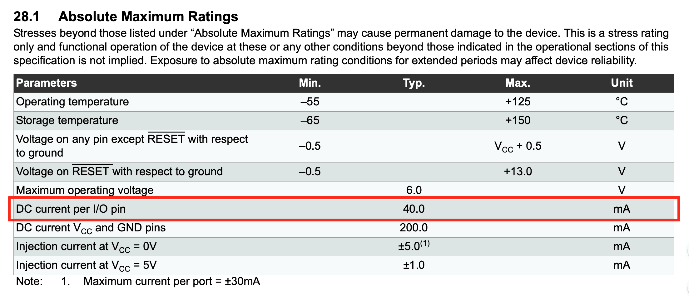
Here we can see that the maximum current that we can source or sink on any IO pin is 40mA. This is plenty for a standard LED that will usually run on somewhere between 5mA and 20mA.
Note that for some chips these the values for source and sink are different. It is more common for the sink current value to be a little higher than the current source value, in cases where the values are different.
Absolute maximum rating
A more important parameter that we must also consider is the maximum DC current between Vcc and GND. This is the total current that the microcontroller draws from the power supply.
This value is also given in the absolute maximum rating table found in the datasheet. In the case of our ATMega328 it is 200mA.
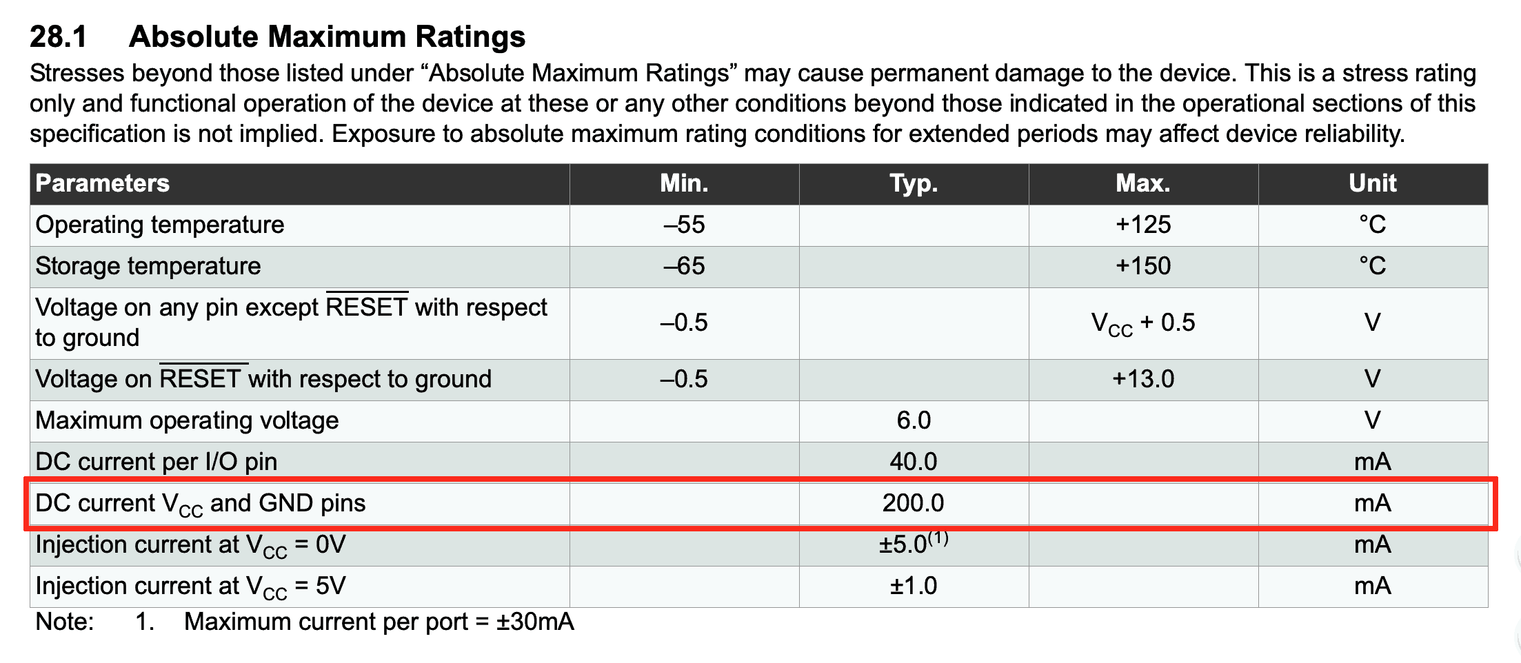
This means that the current sum of all ports should not exceed 200mA.
If we place an LED on each of the 13 digital pins of an Arduino Uno and supply each one 20mA, we will be sourcing or sinking a total of 260mA from the IO pins and exceeding this maximum value! Our Arduino would be toast!
Total number of LEDs
We can say that the total number of LEDs is equal to the total number of digital pins so long as the current on all IO pins does not exceed the maximum DC current on all IO pins.
In the case of our Arduino Uno board with 13 digital IO pins we can divide the total maximum current by 13 in order to see what the maximum current will be for each LED if we use all 13 pins.
300 / 13 = 15.3mA
Note that it would it would not be sensible to run each LED at this current because it would result in a value that is too close to the maximum. In practical electronics design, we need to allow some headroom.
Therefore it would be wise to round this number down to around 10 to 12mA for each LED to stay comfortably within the limit.
So our final answer is that when using only the digital pins on an Arduino Uno board, we can individually control 13 LEDs so long as the current is limited to approximately 10 to 12 mA for each LED.
The easiest way to limit the current on each digital pin is to use a resistor. You can learn about how to choose a resistor value in my tutorial on LEDs and resistors.
Controlling LEDs with Arduino using Multiplexing
What if I told you that it was possible to control more LEDs using only your digital pins, whilst reducing the number of external resistors required?
This is not some kind of wizardry! It is entirely possible using a technique called multiplexing. However as with many things in engineering, there is a tradeoff for increasing the number of LEDs using this technique. Sadly nothing in engineering is for free!
What is multiplexing?
Multiplexing by definition is the process of combining multiple signals into a single signal. A good example is the telephone networks, multiplexing is used in to allow multiple phone calls to travel down a single wire.
However there is always a cost associated with multiplexing and if we wish to transmit multiple calls down a single wire, we sacrifice some of the audio quality.
This is why the sound quality of a traditional telephone call is poor compared with what is possible to produce with a modern audio system.
In the case of multiplexing LEDs, the price we must pay to control multiple LEDs from a single digital pin is reduced brightness.
How does multiplexing LEDs work?
Multiplexing works by organising the LEDs inside a matrix. No, not that matrix, Neo!
We must arrange our LEDs in rows and columns that we can address. Let’s imagine that we have 9 LEDs arranged in to 3 columns and 3 rows.
We need to wire up each row of LEDs to a pin on the microcontroller and each column to a pin on the microcontroller. Here I have represented the digital IO pins with switches.
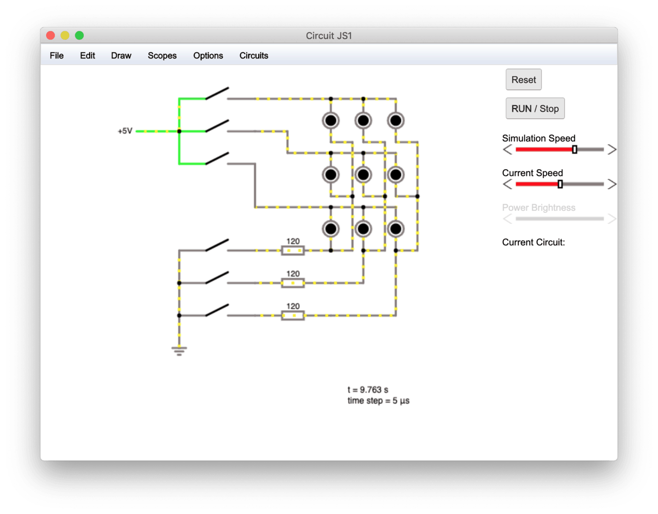
The positive anodes of the LEDs are connected together in rows controlled by the top three switches. The negative cathodes of the LEDs are connected together in columns controlled by the bottom three switches.
The important thing to recognise here is that there are 9 LEDs but only 6 switches. This means that with this configuration we can control 9 LEDs with just 6 pins on a microcontroller.
The benefit here is also squared as you increase the number of pins assuming you are using equal numbers of pins to control the LEDs. For example 5 rows and 5 columns requires 10 pins but can control 25 LEDs!
What you may also notice is that you only need current limiting resistors on either the rows or columns! This means that we only need 3 resistors for 9 LEDs and 5 resistors for 25 LEDs!
The circuit explained
This configuration works using the same persistence of vision technique, the same technique we use to control the brightness of LEDs. Check out this tutorial for a full explanation of how persistence of vision relates to dimming LEDs.
First we enable column 1 in our matrix, then we switch on row 1, 2 and/or 3 depending on which LEDs we would like to illuminate. Let’s say for example we want to illuminate the top two LEDs.
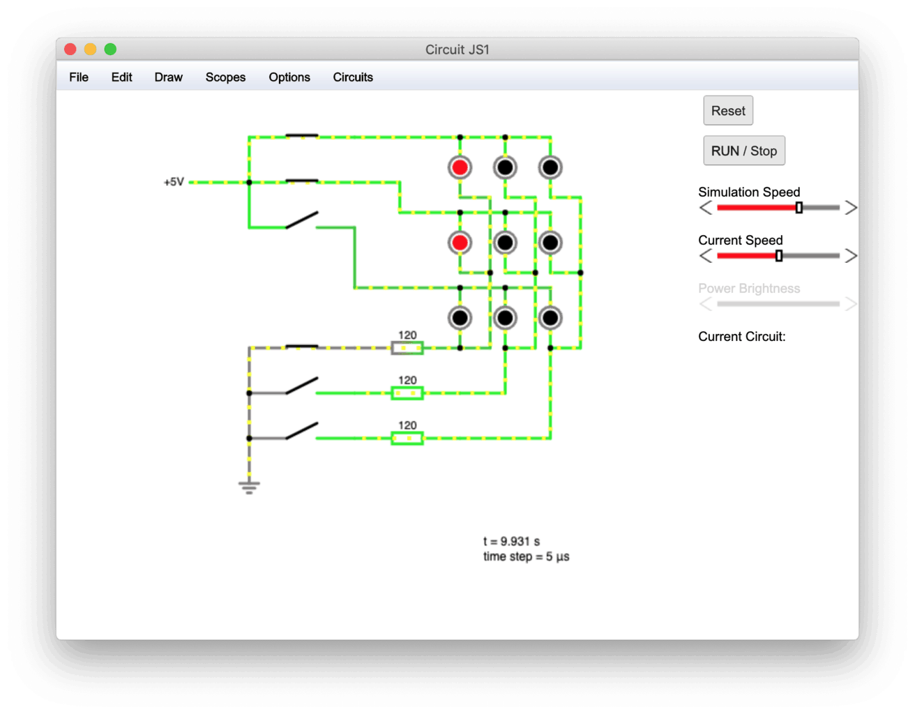
Now we switch off the first column and then switch on the second column. Then we switch on the rows for the LEDs we wish to illuminate. Let’s say for example the middle and bottom LEDs in this column.
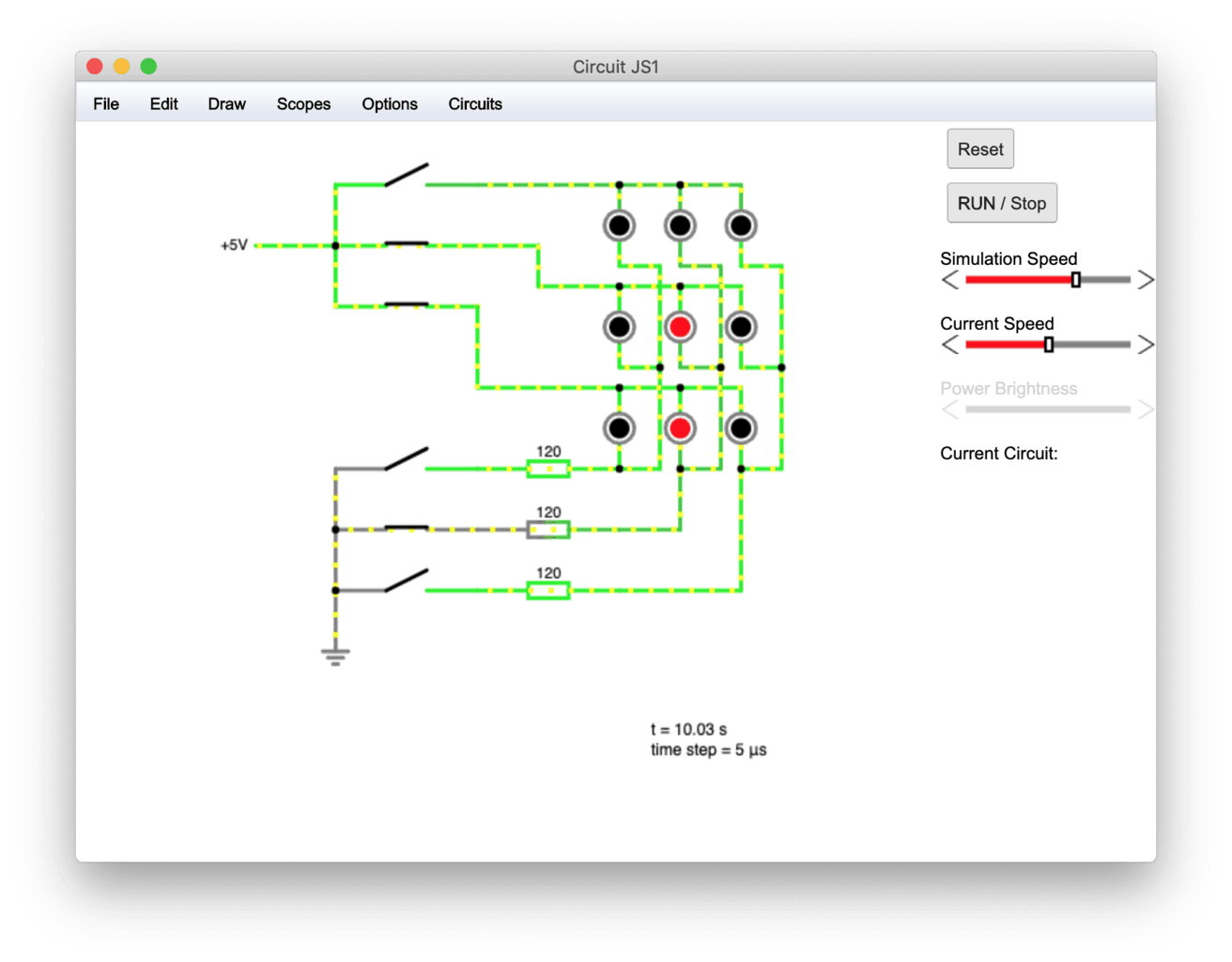
Finally we repeat this for the third column, this time switching on only the middle LED.

As you can see from this example it is possible to control each LED individually using less pins and less resistors!
Now if we write a program on our Arduino that performs this loop very quickly, we will not be able to see the change between each column. Persistence of vision will cause us to see each LED on continuously.
Multiplexing drawbacks
The main disadvantage with this method is that in order to have individual control of each LED, we can only switch on one column at once.
This means that in our example the maximum duty cycle for each LED is 33%, resulting in a maximum brightness of 33% of the total brightness that the LED is capable of.
Further to this the problem magnifies as we increase the number of columns. If we control 25 LEDs with 10 digital pins consisting of 5 rows and 5 columns, our maximum duty cycle for each LED will be 20%. Therefore the LEDs will appear even dimmer.
However for many applications it is still possible to achieve a perfectly acceptable brightness using this technique.
Furthermore the human eye does not have a linear response to brightness. This means that even though we may be operating our LEDs at 20% of their maximum brightness, the eye will perceive less of a decrease in brightness.
This is because the eye is more responsive to changes in dimmer light than it is changes in brighter light.
Shift Registers
The third and final method in this tutorial for controlling multiple LEDs is probably the most powerful and it is the method used by addressable LED strip lighting.
As we get nothing for free in engineering we must pay the price of more complexity, which directly translates to more cost. Although unless you are considering producing a large volume of a particular design, the cost is likely negligible.
Therefore this is my recommended choice for LED control in your projects.
What is a shift register
A shift register is basically a chip with a bunch of digital output pins that take their state from a block of memory called a register.
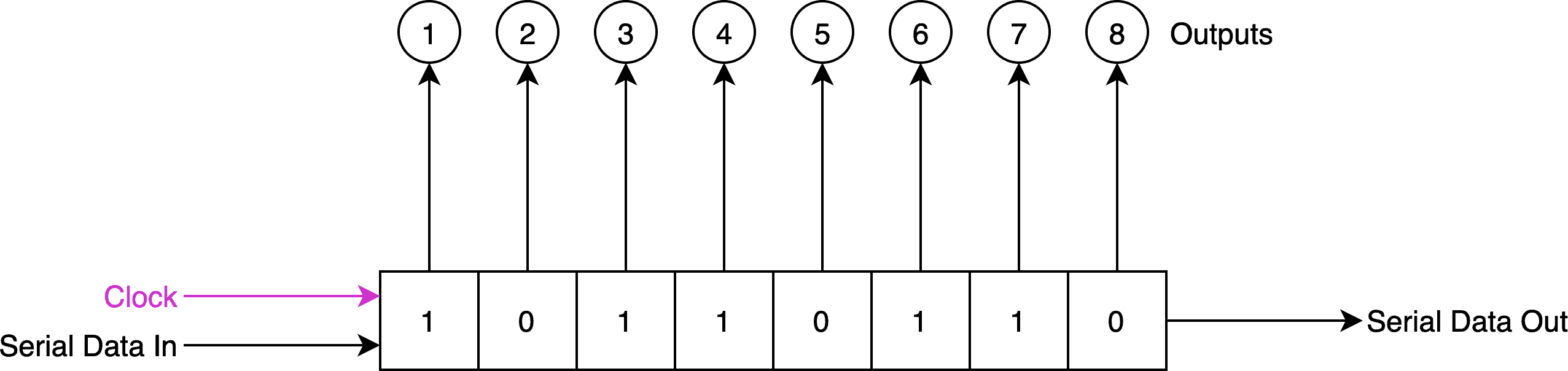
A register is a block of memory that can store a binary number. Each individual binary number is referred to as a bit. A typical shift register has 8 output pins, therefore has an 8-bit register. Each bit represents the state of the corresponding pin.
For example if bit 8 equals “1” then the output pin will be high, usually equal to the supply voltage. If bit 8 equals “0” then the pin will be low, usually grounded to 0 volts.
The state of the set of 8 output pins can therefore be represented by 8 bits, or one byte of data. It is possible to have a larger shift register but 1 byte is most common.
Serial data in
The clever thing about a shift register is the 8 bits of data can be put into the register one after another using as little as 3 pins on the microcontroller. No additional pins are required for increasing the number of LEDs.
There are three main pins that the microcontroller needs to control on the shift register.
- Data – this is the pin that tells the shift register whether the next bit to be put into the register is high or low.
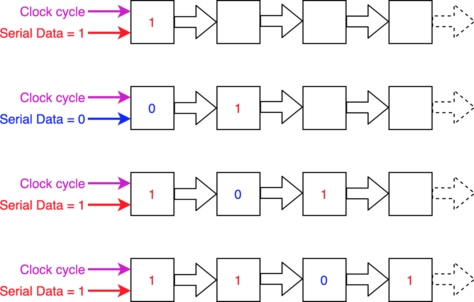
- Clock – the clock pin alternates between high and low. For each cycle the binary numbers are shifted along one place in the register and a new number is inputted into the register. Its value will be equal to the data pin.
- latch – this pin transfers the data from the shift register to the output pins. This allows the 8 bits to be shifted into the correct place before the state of the output pins is updated.
When the data is shifted along in the register a new bit enters at the start of the register depending on the state of the data pin. The bit at the end of the register is discarded.
Data latch
There is also an additional pin called the latch pin, which shifts the data from the register to the output.
This means we can clock in all of our data without affecting the state of the outputs. Then once all the correct data has been shifted into the register, the outputs can be updated with the new data.
When the latch pin is low, data can be shifted into the register independently of the outputs. If we are using a shift register to control LEDs it will prevent the LEDs from flickering as data is transferred.
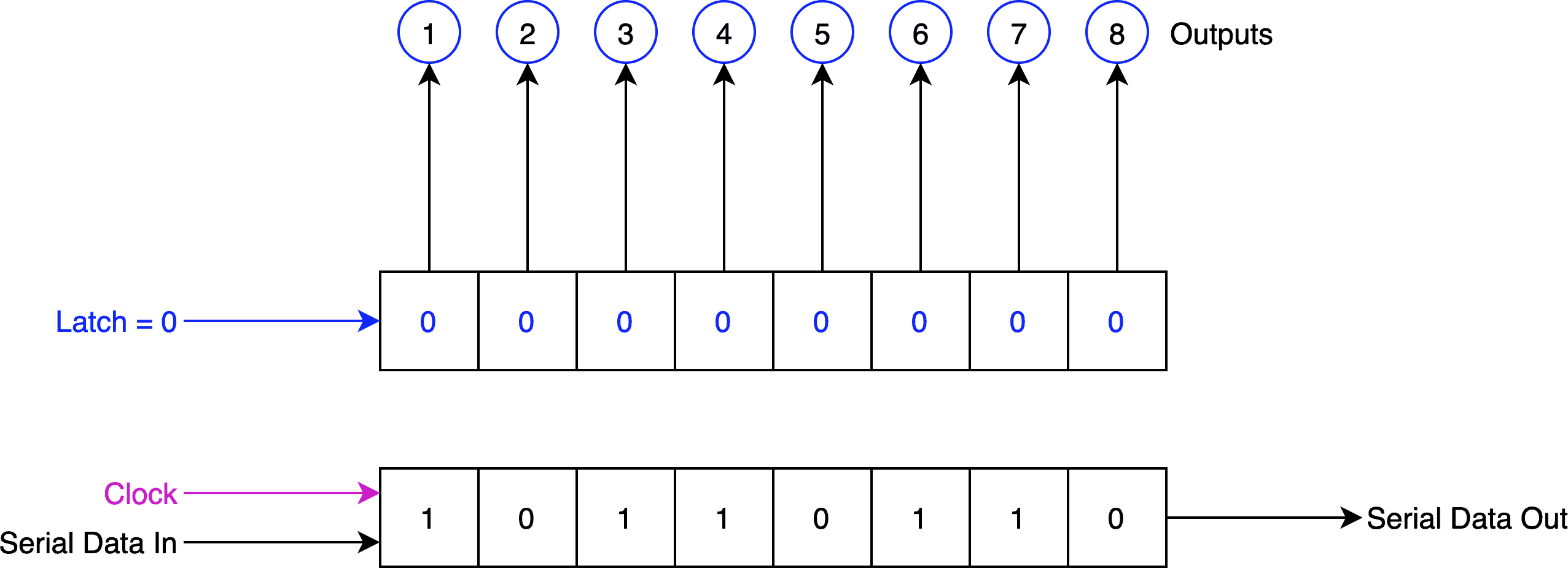
Once all of the data is lined up correctly in the data register, the latch pin can be set to high to move the data to the outputs.
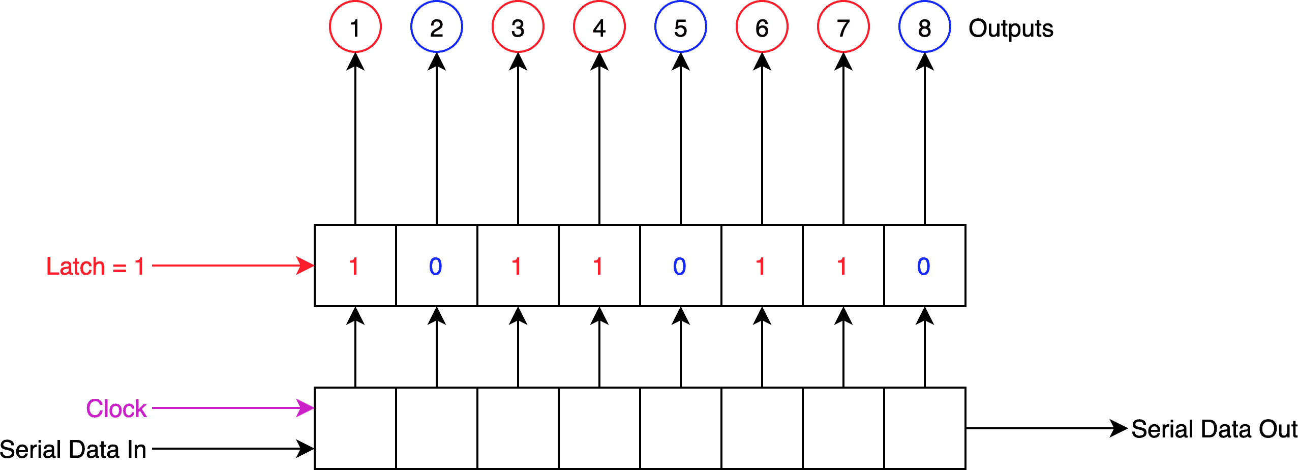
As the outputs can maintain their state whilst the new set of data is being shifted into the register, the LEDs can remain illuminated.
This means that the shift registers do not suffer from the same drawback as multiplexing, where the maximum brightness decreases as more LEDs are added to the system.
Serial data out
Shift registers usually have an output pin, whereby the state of the pin is set by the bit that is discarded from the end of the register.
We can connect this output pin to the input pin on another shift register. Therefore rather than discard the end bit as the data is shifted, the bit simply moves to the first location in the next shift register.
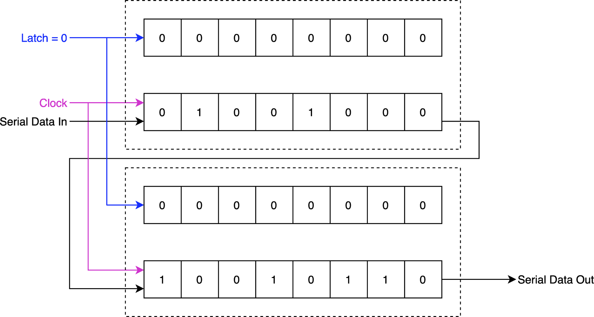
This is a powerful feature of the shift register. It means we can tie many shift registers together in series.
In the context of controlling LEDs we can put an LED on each output of the shift register and then place many shift registers in sequence, increasing the number of LEDs without increasing the number of digital pins required.
This leads to us being able to control a huge amount of LEDs with only a few digital pins on the microcontroller.
Shift register LED drivers
Another benefit of shift registers is that there are specific variants that are designed to drive LEDs.
These shift registers have built-in constant current driver pins. This means that the outputs are designed to limit the current driving LEDs connected to the output pins using specific internal circuitry.
These shift registers do not need the LEDs to be connected to current limiting resistors, reducing the complexity and component count somewhat. Usually a single resistor is connected between a pair of additional pins on the chip, which define a global current limit for each output.
The Texas Instruments TLC591X is a great chip to start with if you are new to using shift registers.
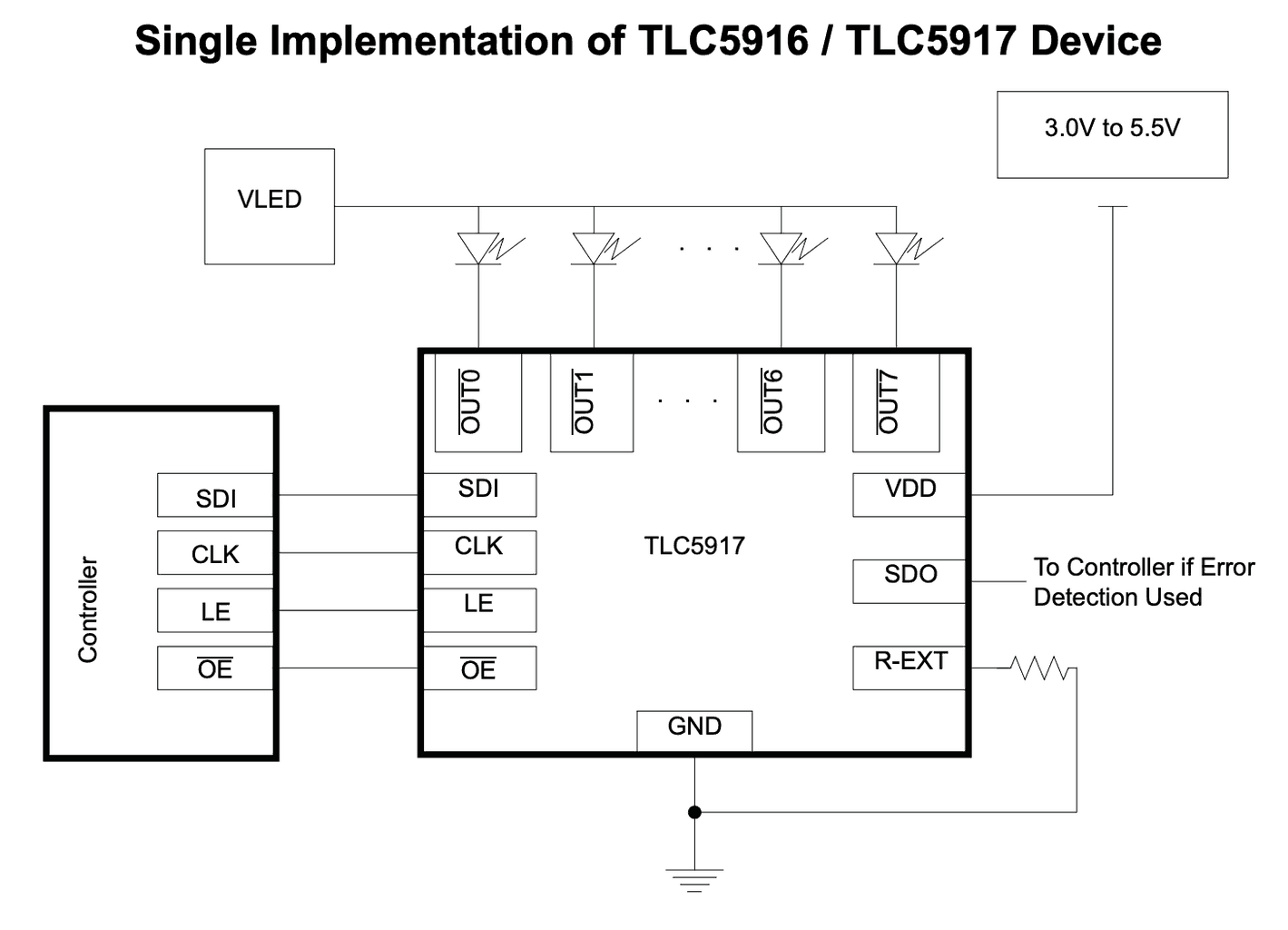
It can be controlled by any microcontroller using 3 digital pins, however a fourth pin can be used to disable the outputs if desired.
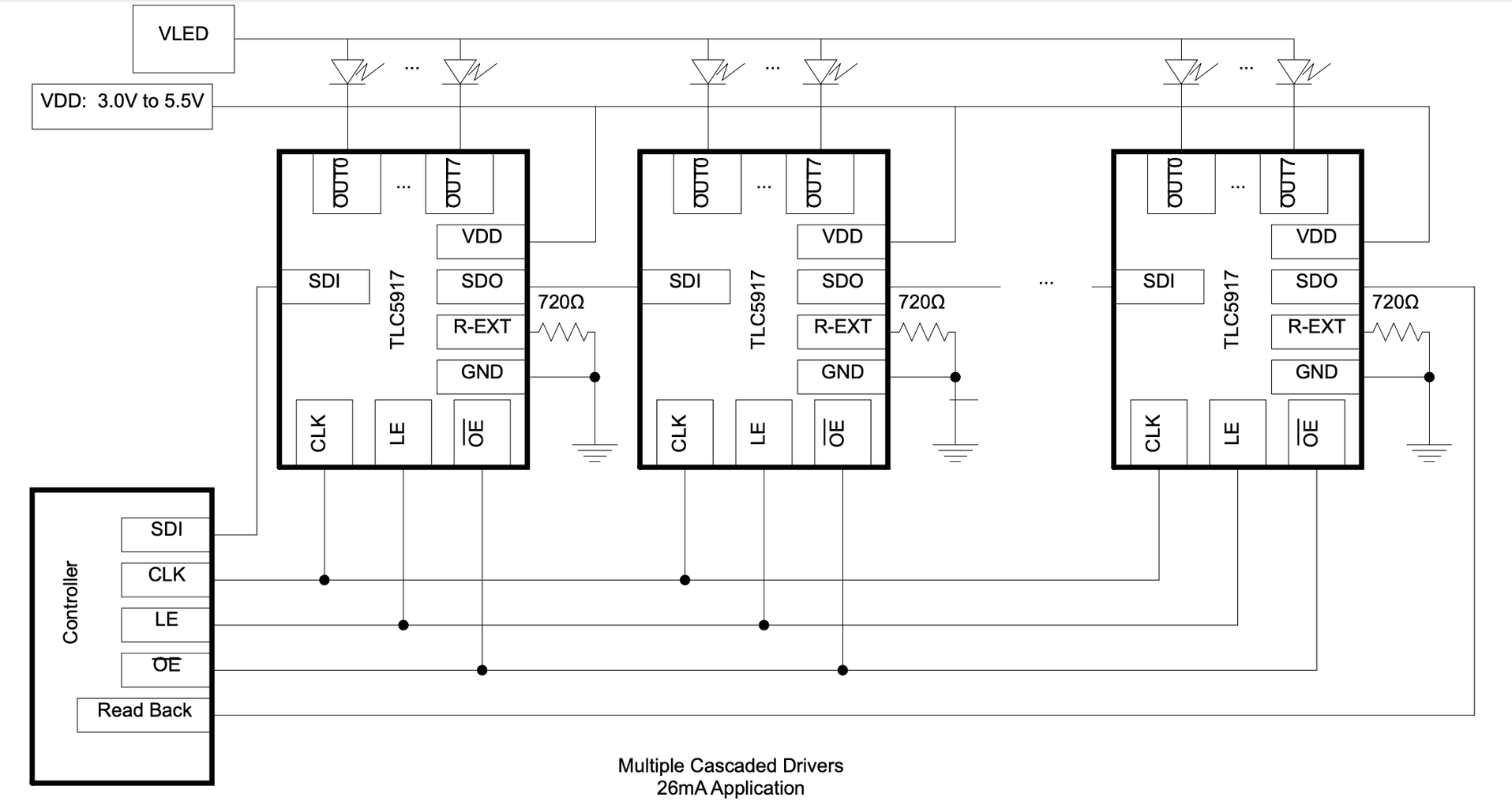
A single resistor is used to set the global current limit for the LEDs and it has a serial output for cascading multiple chips together, as shown in the following diagram.
Drawbacks
There are a couple of drawbacks to consider if you choose to use shift registers for driving multiple LEDs.
Firstly the most obvious drawback is you need to use a driver chip for every 8 LEDs. Although there are less resistors required it is still the most complex and costly way of the methods we have looked at to add LEDs to a microcontroller.
Secondly there is an upper limit to the speed in which you can clock data into the chip.
It is still relatively high and generally in the tens of megahertz range, but if you wish to control a large quantity of LEDs such as in an LED matrix display it can have a notable impact on the colour depth or refresh rate of the display.
Conclusion
In this tutorial we have learnt that it is possible to easily control a large number of LEDs with a basic microcontroller, such as those found on the Arduino boards.
Different methods have different benefits and drawbacks, therefore it is a good idea to pick a method best suited to your application.
If you enjoyed learning about LEDs in this tutorial, why not go ahead and check out my other tutorial on LEDs and resistors.
Article Updates
July 26th 2023 : Formatting updated, minor edits. Featured image updated. TOC added.
Article first published February 27th 2020.
Thanks so much for visiting my site! If this article helped you achieve your goal and you want to say thanks, you can now support my work by buying me a coffee. I promise I won't spend it on beer instead... 😏