It is acceptable to use an LED without a resistor, but some method of limiting the current must be used in order to prevent the device from being destroyed. Failure to limit the current could lead to the device burning out, failing prematurely or even exploding.
I have certainly blown up a few LEDs in my younger and more inexperienced years, causing part of the casing to shoot across the room in spectacular fashion!
In many applications the easiest way to regulate the flow of current through the LED is to use a resistor, although there are more sophisticated methods such as using a constant current driver.
In this tutorial we shall take a look at why it is necessary to limit the current flowing through the LED and how we can select the correct resistor, so you can avoid having your project go up in smoke.
- What is a LED?
- LED Characteristics
- Calculate the resistance
- Resistor Heat dissipation
- Do I REALLY need a resistor?
- What Happens if I Connect the LEDs Directly to the Arduino Without Resistors?
- What Will Go Wrong if I Connect an LED Directly to a Battery Without a Resistor?
- Do I Need a Resistor For An RGB LED?
- Is There Any Situation Where It Might Be Suitable to Use an LED Without a Resistor?
- What Happens if You Use The Wrong Resistor with an LED?
- What Happens If I Put Too Little Voltage Through an LED?
- Conclusion
What is a LED?
If you didn’t already know, LED stands for light emitting diode. It is a semiconductor device that can turn electrical current in to light.
Utilising different semiconductor materials allows LEDs to be manufactured to produce different colours.
However up until the mid-90s LEDs had a limited range of colours such as red, green and yellow. Most notably it was not possible to produce blue.
Developments in LED technology and the introduction of new materials in the manufacturing process expanded the range of available colours. One of the greatest developments in LED technology was the introduction of Indium gallium nitride.
This allowed the production of blue LEDs, completing the range of primary colours available, red, green and blue. It was then possible to manufacture RGB LEDs, which can produce the whole colour spectrum.
This opened up many applications that we have become familiar with.

Following this development came advancements in brightness and also the white LED. Once the technology had progressed this far, the LED bulb became a reality and LED lighting was set to replace the incandescent bulb.
Now there are a wide range of different types of LED available containing various type of material. As these utilise different materials, some of the electrical characteristics are different.
It is important to understand the basic characteristics in order to calculate the value of the current limiting resistor and design a circuit that will power your LED correctly.
LED Characteristics
The LED is a beautifully simply component and requires minimal electronics knowledge to utilise, whilst giving exciting end results to the most basic of electronics project.
The single colour variant features only two pins and only requires one other component to function, the current limiting resistor. It also looks cool because, well… it’s a LED!
Each LED has two pins, the positive anode terminal and the negative cathode terminal. As the LED is a diode, the polarity must be correct in order for current to flow.

There are three fundamental things that we need to understand in order to calculate the size of the current limiting resistor.
- Ohm’s law
- Watt’s law
- Forward voltage and current
Once we understand these principals and can calculate the size of our current limiting resistor, we can understand why it is necessary to use the resistor (assuming a simple circuit that does not use a constant current driver).
Ohm’s law
Ohm’s law is probably the most fundamental principle in electronics. It describes the relationship between voltage, current and resistance.
If you are new to electronics it can sometimes be hard to visualise what exactly is happening ‘inside the wires,’ but this well known cartoon drawing sums it up perfectly.
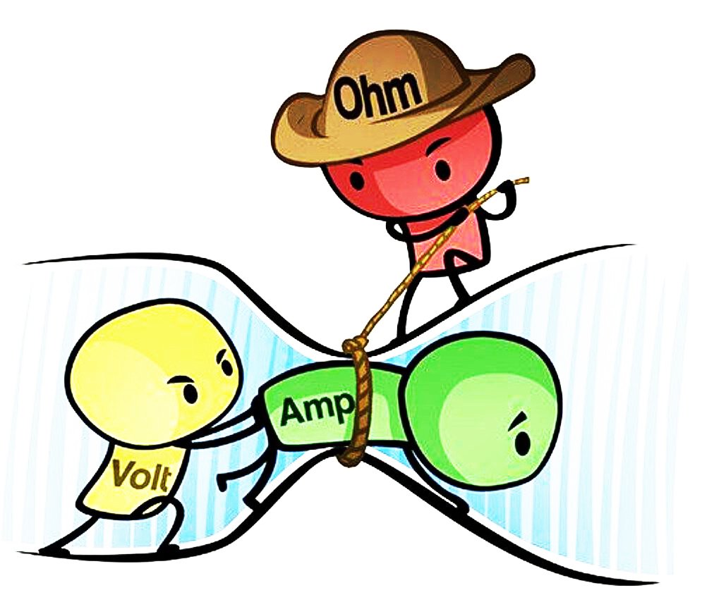
We can describe this principal with in basic mathematical terms, the voltage is equal to the current multiplied by the resistance.
voltage (V) = current (I) x resistance (R)
In the case of our LED circuit, we can use Ohm’s to calculate the value for our current limiting resistor using known values for voltage and current.
Watt’s law
Watt’s law describes the relationship between power, voltage and current. It is a measurement of the quantity of energy used over time.
1 Watt = 1 Joule per second
In simple mathematical terms we can say that the power is equal to the voltage multiplied by the current.
power (W) = voltage (V) x current (I)
Note that it is possible to substitute between Ohm’s and Watt’s law. You will notice that both laws have current (I) and voltage (V). For example you can substitute the voltage in Watt’s law for current multiplied by resistance from Ohm’s law, as current multiplied by resistance equals voltage.
V = I x R
P = I x V
therefore,
P = I x (I x R)
In the case of our LED circuit, we need to use Watt’s law to calculate the power dissipated by the resistor.
When current flows through a resistor the power is dissipated as heat, therefore we must ensure that our resistor is capable of dissipating a large enough amount of power as heat without being destroyed or becoming excessively hot.
Forward voltage and current
The forward voltage and forward current of the LED are the two properties that we need in order to calculate the required resistance.
When applying a voltage across the LED, some of the voltage is ‘lost’ due to the characteristics of the LED. We call this the voltage drop and the amount of voltage that is dropped is dependent on the materials used in its construction, and therefore it’s colour. This voltage is known as the forward voltage and is denoted as Vf.
The forward current is a value used to describe the amount of current we must supply the LED in order for it to illuminate to it’s optimum brightness. We must limit the current flowing through it with an external component, in our case the current limiting resistor.
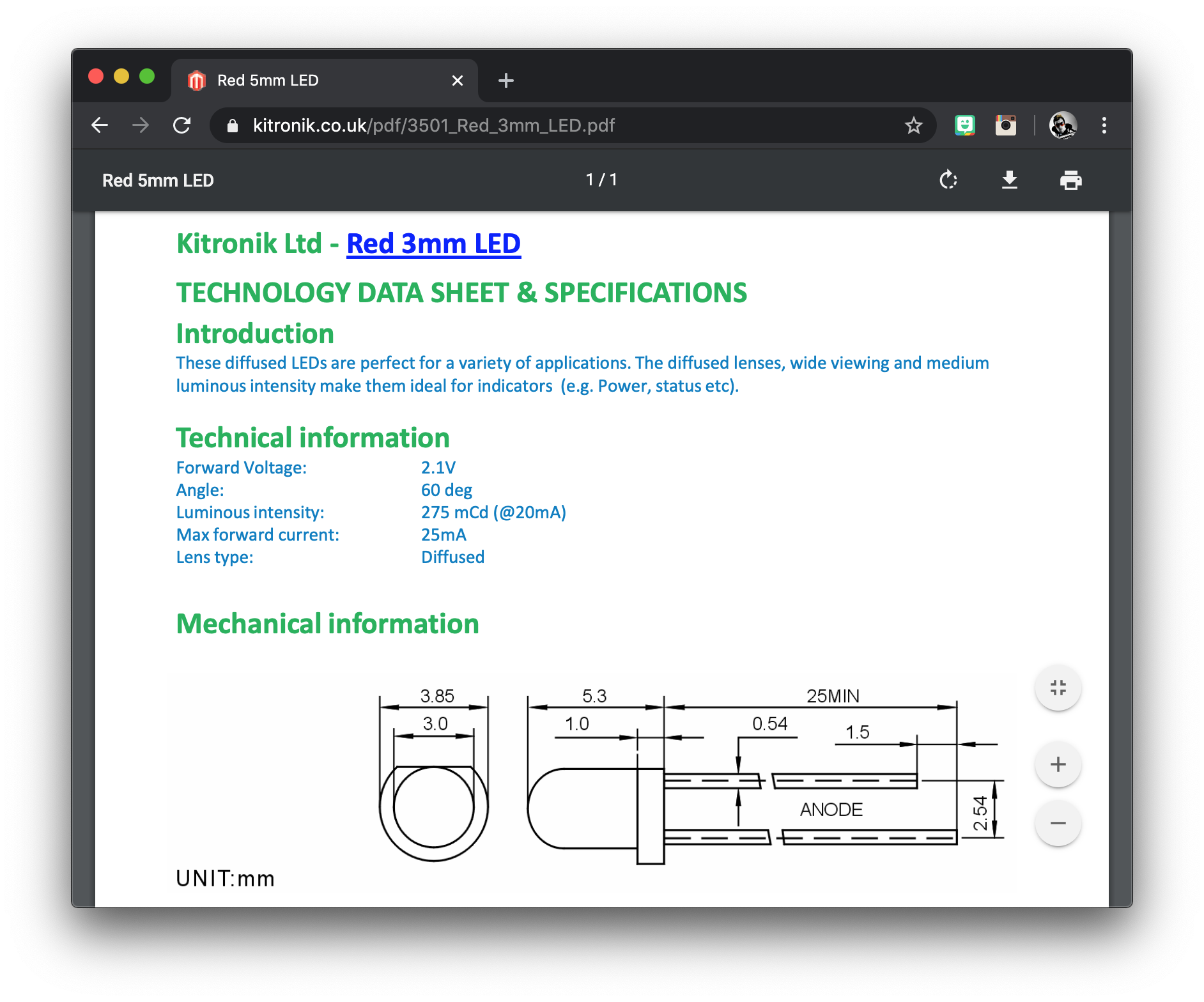
Both of these values are given in the datasheet, a technical document usually supplied with all components that the circuit designer can use to obtain the technical details necessary to design a circuit using the particular component.
For our example we will use a standard red LED. As shown in the following datasheet we can see it has a forward voltage of 2.1 volts and a forward current of 25 milliamps (the same as 0.025 amps). These values are fairly common for a standard red LED.
Calculate the resistance
We know from the datasheet that the forward current should be 25mA, which we will use as the desired resistance value in our Ohm’s law equation.
However the forward voltage does not give us the necessary value for our Ohm’s law voltage value, and we must also consider the power supply voltage.
For this example we will use 5 volts for the LED power supply, as this is a common voltage used by microcontrollers and it is likely you will want to use it to control your LEDs. You can of course choose any suitable voltage for your application.
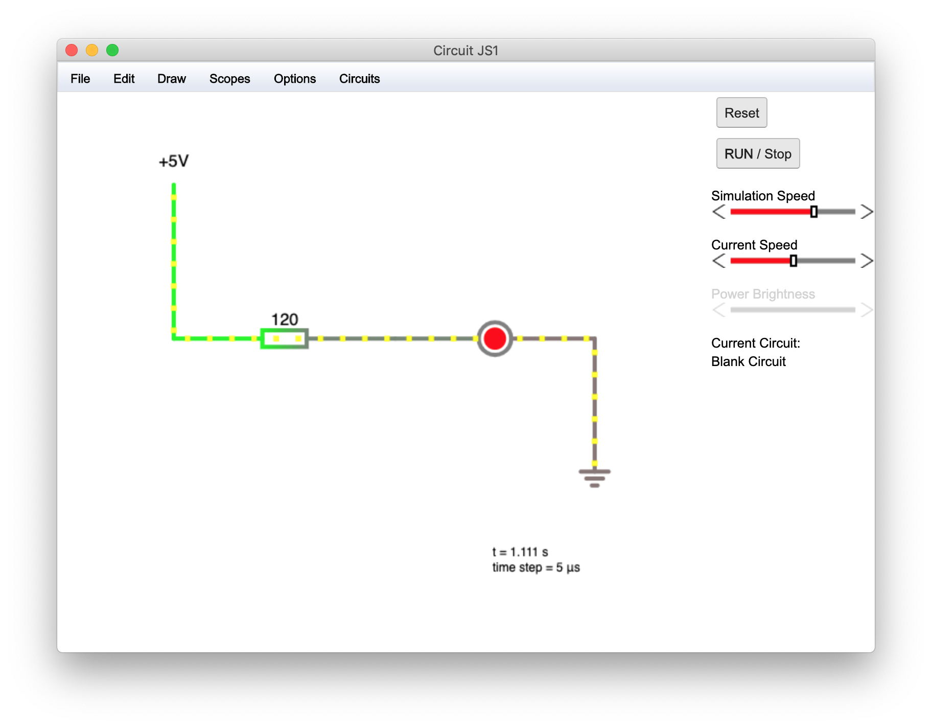
We will wire our components in series so that the current flows from the positive terminal of our power supply, through the resistor, then the LED and then to ground.
It does not matter whether the resistor is placed before or after the LED as the current remains constant for components wired in series.
As previously mentioned there will be a voltage drop across the LED equal to the forward voltage. The forward voltage is given in the LED datasheet.
Vf = 2.1V
The remaining voltage appears across the resistor, therefore if we deduct the forward voltage from the supply voltage, we can calculate the voltage across the resistor, Vr.
Vr = V - Vf
Vr = 5 - 2.1
Vr = 2.9
We want to supply the LED with the forward current value given in the datasheet, 25mA. As the resistor will limit the current we must use the voltage across the resistor and the desired forward current in our Ohm’s law equation.
Now we can calculate the resistance by rearranging the Ohm’s law equation in terms of resistance (the forward slash denotes ‘divided by’). Remember we must convert milliamps to amps, just divide by 1000.
25mA = 0.025 A
R = Vr / I
R = 2.9 / 0.025
R = 116 ohms
Now we know that in order to provide the LED with 25mA we must use a resistor with the value 116 ohms. It is always best to exercise a little caution as resistance values have a tolerance and may vary slightly from the given value.
In a practical sense we should round up this value to the nearest common resistor value. It is important to round up and not down, as if we rounded down we would be supplying more than the recommended current to the LED.
We shall use a value from the E12 resistor values, giving us the nearest higher value of 120 ohms.
Resistor Heat dissipation
Unlike the LED, which converts electrical current to light (and some heat), the resistor converts electrical current almost entirely to heat.
We know the voltage across the resistor and the current flowing through it (and the LED). We can use Watt’s law to calculate the power dissipated by the resistor.
P = I x V
P = 0.025 x 2.9
P = 0.0725
The resistor will dissipate 0.0725 watts of power as heat, also written as 72.5 milliwatts (mW).
Therefore when we choose a resistor, we need to check the datasheet to see if it can dissipate 72.5mW of heat without being damaged.
Smaller standard resistors can usually dissipate 125mW (also stated as 1/8th of a Watt), therefore our combination of LED, resistor and power supply will work well.
Do I REALLY need a resistor?
One question I have seen asked several times but one that is rarely explained in similar tutorials concerns a scenario where the forward voltage equals the supply voltage.
Let’s do the maths to see what this looks like on paper. For this example we will use a blue LED with a forward voltage of 3.3V and a forward current of 25mA.
For the power supply we will use 3.3V, a common supply voltage found in microcontroller circuits.
First we calculate the voltage across the resistor.
Vr = V - Vf
Vr = 3.3 - 3.3
Vr = 0V
Now we can use Ohm’s law again to calculate the required value of resistance for the known voltage across the resistor and desired current.
R = Vr / I
R = 0 / 0.025
R = 0 ohms
What?! Haven’t we just proven with Ohm’s law that no value of resistance is required and thus no resistor is required if the supply voltage and forward voltage are equal?
It is easy to see why so many people reach this conclusion using the basic electronics principles. I myself once asked the same question!
In fact I recently saw someone ask this question in a forum, which is what inspired me to write this article.
Real world application
The first thing to remember is we are dealing with absolute numbers in our calculations but in the real world your 3.3V supply will probably not be exactly 3.3V. It may be 3.34V and likewise the forward voltage will not be exact, it may be 3.28V.
Next we need to consider a scenario where no resistor is present in the circuit. In this case the resistance governing the flow of current through the LED will be the internal resistance within the LED itself.
Note that in the practical application, the LED internal resistance is summed with the value of resistance chosen for the current limiting resistor.
However the value is so small, it is almost always ignored as it makes no noticeable difference to the calculation.
Internal resistance
So what happens if we rely on the internal resistance within the LED? First we must calculate the internal resistance. This can be done using the forward current vs forward voltage data from the datasheet.
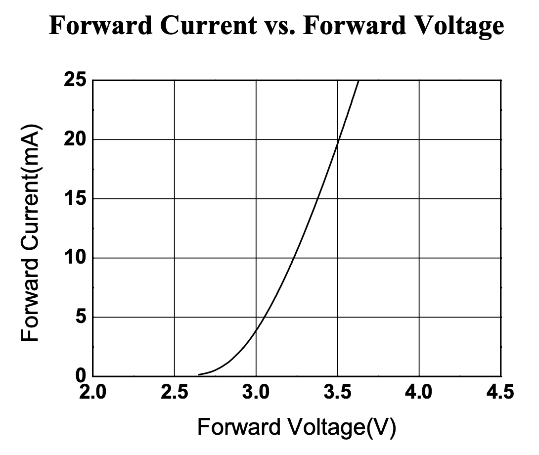
First let’s choose two voltage points on the graph in the linear region. We will choose 3.25V and 3.5V. Then let’s make a note of their current values, 10mA and 20mA respectively.
The difference between these values is 0.25V and 10mA. We can use these values with Ohm’s law to calculate the internal resistance.
R = V / I
R = 0.2 / 0.015
R = 25 ohms
Next we need to calculate the LEDs intrinsic voltage, Vint. This is the voltage across the LED and can be subtracted from the supply voltage to get the voltage across the internal resistance.
Vint = Vf - (If x Rint)
Vint = 3.25 - (0.01 x 25)
Vint = 3 V
Don’t worry if you didn’t follow all of that, it is a little more advanced than the scope of this tutorial, but I thought I would include it anyway.
Let me clarify things a little. There are two values here that are important, the intrinsic voltage Vint and the internal resistance Rint.
This is the same as our earlier example, only it is the voltage and resistance for the internal resistance of the LED, rather than an external resistor.
Vint = 3 V
Rint = 25 ohms
The calculation for current flow through the LED is the same as before, we use Ohm’s law to calculate the value of current using the values above.
Let’s try it with an arbitrary supply voltage of V = 3.5 V. First we subtract Vint from V to get Vr = 0.5 V. Then we can use this voltage with the internal resistance to calculate the current.
I = Vr / Rint
I = 0.5 / 25
I = 0.02 A
As expected we get 20mA, matching the graph. However in the real world our supply voltage will not be exact. Therefore let’s calculate for 3.4 V, a 100mV difference.
First we subtract Vint to get 0.4 V, then we calculate the current again using the internal resistance.
I = Vr / Rint
I = 0.4 / 25
I = 0.016 A
As you can see we have a noticeable change in current for only a small change in voltage.
Comparison
Finally we can compare the result with and without the resistor. We know that a drop in voltage of 100mV can reduce the current flowing through the LED with no external resistor by 4mA.
External resistor and 12 V supply
First we calculate the size of the resistor required to achieve 20mA of current through the LED using the typical forward voltage of 3.3 V given in the datasheet. We can use an arbitrary power supply voltage of 12 V.
R = (V - Vf) / I
R = (12 - 3.3) / 0.02
R = 435 ohms
Now we can simulate the same drop in supply voltage. The forward voltage of the LED is fixed, therefore the 100mV drop will affect the voltage across the resistor. This in turn will affect the current flowing through the LED and is calculated as follows.
I = ((V - Vf) - 100mV) / R
I = 8.6 / 435
I = 0.0198
The result shows that we only experience a 200 nanoamp reduction in current, or 0.2mA.
External resistor and 24 V power supply
It is also worth noting that the more voltage across the resistor, the less difference a change in supply voltage will make.
For example if we increase our supply voltage to 24 V, the 100mV drop in supply voltage will make the following difference to the current.
R = (V - Vf) / I
R = (24 - 3.3) / 0.02
R = 1035 ohms
I = ((V - Vf) - 100mV) / R
I = 20.6 / 1035
I = 0.0199
Now we can see that with a 24 V power supply we only see a difference in current of 100nA, or 0.1mA!
Don’t forget the heat dissipation!
So the higher the supply voltage the better, right? Well, not exactly because you still need to consider heat dissipation.
Using a 24 V power supply with an LED that has a 3.3 V voltage drop will mean there will be 20.7 V across the resistor. How much heat must it dissipate?
P = I x V
P = 0.02 x 20.7
P = 0.414 watts
Our resistor needs to be rated for at least 500mW or 1/2 a watt. Even this is quite close to the requirement and therefore the resistor will get hot.
As with many things in electronics, there is always a trade-off and you must select the correct component values to get the best compromise.
What Happens if I Connect the LEDs Directly to the Arduino Without Resistors?
If you connect LEDs directly to the Arduino pins without resistors, it can lead to several undesirable consequences:
- LED Burnout: The most immediate consequence would be that the LEDs may burn out or get permanently damaged. LEDs have a specific current rating that should not be exceeded. Without a resistor, the current flowing through the LED would be unregulated, and it could draw more current than it can handle, causing it to fail.
- Risk to the Arduino: Without a current-limiting resistor, the Arduino pins could be exposed to excessive current draw, which can damage the microcontroller or its output pins. While Arduinos have some built-in protection, it’s not enough to handle a significant amount of current.
- Inconsistent Brightness: LEDs have a nonlinear voltage-current relationship, so slight voltage changes can result in significant current changes. If you connect LEDs directly without resistors, their brightness may be inconsistent, and some LEDs may appear much brighter than others.
- Unpredictable Behavior: The Arduino may behave unpredictably or erratically if the current drawn from the pins exceeds their specified limits. This could lead to a malfunction of the Arduino or the other components connected to it.
To safely use LEDs with an Arduino or any other microcontroller, it’s essential to include current-limiting resistors in the circuit.
The resistor value can be calculated using Ohm’s law, taking into account the forward voltage drop of the LED and the desired current through it.
By adding the appropriate resistor in series with each LED, you can ensure that they operate within their safe operating limits, and you protect both the LEDs and the Arduino from damage.
What Will Go Wrong if I Connect an LED Directly to a Battery Without a Resistor?
If you connect an LED directly to a battery without a current-limiting resistor, several things can go wrong:
- LED Burnout: The most immediate consequence is that the LED may burn out or get permanently damaged. LEDs have a specific current rating that should not be exceeded. Without a resistor to limit the current, the LED would draw more current than it can handle, causing it to fail.
- Risk of Battery Damage: Drawing excessive current from the battery can also damage the battery itself. Batteries are not designed to supply extremely high currents continuously, and doing so can shorten their lifespan or even cause them to leak or overheat.
- Unsafe and Unpredictable Behavior: Without a current-limiting resistor, the LED’s current draw would be unregulated, and the LED might become extremely bright for a brief moment before burning out.
- Overheating Components: Connecting an LED without a resistor can also lead to other components in the circuit getting damaged or overheated due to the high current flow.
To safely use an LED with a battery or any power source, it’s crucial to include a current-limiting resistor in the circuit.
The resistor’s value can be calculated using Ohm’s law, taking into account the forward voltage drop of the LED and the desired current through it.
By adding the appropriate resistor in series with the LED, you can ensure that it operates within its safe operating limits and prevent any damage to the LED or the power source.
Do I Need a Resistor For An RGB LED?
Yes, you typically need a resistor for each color channel (Red, Green, and Blue) of an RGB LED to limit the current and prevent damage to the LED and other components in the circuit.
RGB LEDs are composed of three individual LEDs, one for each color channel. Each color LED has a specific current rating that should not be exceeded.
If you connect an RGB LED directly to a power source without current-limiting resistors, several problems can occur:
- Burnout: The LEDs may burn out or get permanently damaged due to excessive current flow.
- Inconsistent Colors: RGB LEDs are commonly used to create different colors by adjusting the intensity of each channel. Without resistors, the LEDs may draw different currents, leading to inconsistent brightness and color balance.
- Circuit Overload: Drawing excessive current can overload the power source or other components in the circuit.
To properly use an RGB LED, you should include a resistor in series with each color channel. The resistor value can be calculated using Ohm’s law, taking into account the forward voltage drop of the LED and the desired current through it.
Using resistors will ensure that each color channel operates within its safe operating limits and provide consistent and controlled color mixing.
Is There Any Situation Where It Might Be Suitable to Use an LED Without a Resistor?
Using an LED without a resistor is generally not recommended due to the risks of damaging the LED and other components in the circuit.
However, there are a few specific scenarios where it might be considered suitable to use an LED without a resistor.
Some electronic devices, such as switches or indicators, may have built-in circuitry that includes a current-limiting resistor to drive the LED safely. In these cases, the LED is designed to operate without the need for an external resistor.
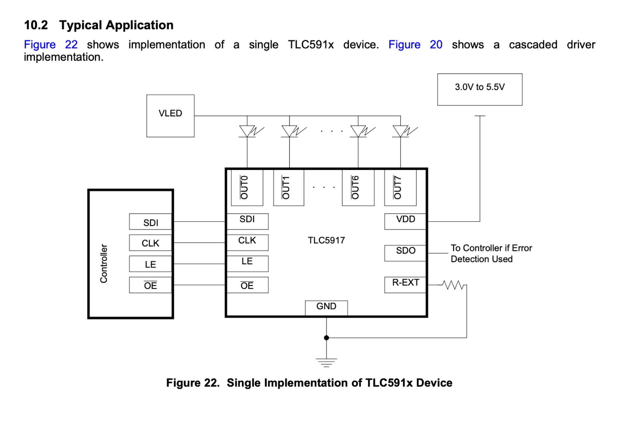
Many LED driver chips contain all of the necessary circuitry to limit the current provided to the LED that is connected to it. When using these devices, you do not need to use a current limiting resistor.
An example of such device is the TLC5917 8-bit constant-current LED sink driver, which is designed to illuminate up to 8 LEDs and can be controlled with just a couple of microcontroller pins.
Taking a closer look at the datasheet shows the LEDs connected directly to the chip for typical applications.
What Happens if You Use The Wrong Resistor with an LED?
Using the wrong resistor with an LED can have several consequences, depending on whether the resistor is too high or too low in value:
- High-Value Resistor (Too Much Resistance): If you use a resistor with a value that is too high, it will limit the current flowing through the LED too much. This can result in the following outcomes:
- Dim or Off LED: The LED may appear very dim or may not light up at all because the limited current is insufficient to illuminate the LED.
- Inconsistent Brightness: Different LEDs in the same circuit may have varying brightness levels if they are not matched correctly due to the varying forward voltage of different LEDs.
- Low-Value Resistor (Too Little Resistance): If you use a resistor with a value that is too low, it will allow too much current to flow through the LED, leading to the following issues:
- Overheating: The LED can overheat and get damaged because it’s receiving more current than it is designed to handle, shortening its lifespan or causing immediate failure.
- Burnout: Excessive current can lead to permanent damage or burnout of the LED.
In both cases, using the wrong resistor can lead to the LED failing prematurely or not performing as intended.
To ensure proper operation and longevity of the LED, it’s essential to use the correct resistor value. The resistor value can be calculated using Ohm’s law, considering the forward voltage and desired current through the LED.
Always choose the nearest standard resistor value available if an exact value is not available. Additionally, when working with multiple LEDs in a circuit, it’s essential to match their characteristics and use corresponding resistors to achieve consistent brightness and performance.
What Happens If I Put Too Little Voltage Through an LED?
If you put too little voltage through an LED, it may not light up or emit light very dimly. LEDs have a specific forward voltage (Vf) requirement, which is the minimum voltage required for them to start conducting and emit light.
When the voltage across the LED is below its forward voltage, the LED remains in a non-conductive state, and only a tiny leakage current flows through it.
This leakage current is usually negligible and insufficient to produce any visible light. Instead, the LED might appear dark or off.
The exact forward voltage (Vf) of an LED depends on its material and color. Typically, for standard LEDs, the forward voltage ranges from around 1.5 to 3.5 volts.
If the LED is designed for a higher voltage than the one provided, it might not operate at all or may only emit a faint glow.
It’s essential to provide the LED with the correct forward voltage to ensure proper operation and light emission. This is typically achieved by using a power supply or voltage source that at least slightly exceeds the LED’s forward voltage requirement.
Also it is important to understand that when using an LED with a current limiting resistor, the LED forward voltage is deducted from the total supply voltage, leaving the remaining voltage across the current limiting resistor.
In order for the current limiting resistor to function correctly, it must have adequate voltage across it. Therefore it would be recommended to use a supply voltage of at least 1.0V greater than the LED forward voltage.
Conclusion
It is important to regulate the current flowing through a LED in order for it to function consistently and correctly. It is perfectly acceptable to limit the current by means of a resistor, or other current regulating device.
Theoretically it would be possible to limit the current using the internal resistance of the LED, but in reality is it just not practical to do so. The voltage would need to be very precise.
It would also need to be tuned to each LED to match the exact forward voltage characteristic, which would also differ for each LED due to the manufacturing tolerances involved in producing the LED.
The most simplistic way to prevent your LED meeting a premature death or even exploding, is to use a current limiting resistor!
I hope this tutorial was insightful and gave you some new and useful knowledge about the humble and ubiquitous LED! Please take some time to visit some of my other cool tutorials!
Article Updates
July 27th 2023 : Frequently Asked Questions added. Featured image updated. TOC added.
Article first published February 14th 2020.
Thanks so much for visiting my site! If this article helped you achieve your goal and you want to say thanks, you can now support my work by buying me a coffee. I promise I won't spend it on beer instead... 😏