
Welcome to the comprehensive guide on LED dimming and the fascinating world of Pulse Width Modulation (PWM).
LED lighting has revolutionized the way we illuminate our surroundings, providing energy-efficient and long-lasting solutions. But have you ever wondered how LEDs can smoothly change their brightness?
That’s where PWM comes into play. In this article, we will delve into the inner workings of LED dimming, exploring the principles of PWM, its advantages, and how it enables us to control the intensity of light in various applications.
Whether you are a curious enthusiast or budding electronic engineer, join me as we shed light on the intricacies of LED dimming through the lens of Pulse Width Modulation. Let’s get started!
What is Persistence of Vision And Why is it Important?
Persistence of vision is somewhat of an optical illusion, whereby light entering the eye is perceived to be still present for some time after the the light ceases to enter the eye.
What this means is if you were to look at a lamp that was flashing at an increasing rate, there would come a point where the lamp was flashing so quickly it would appear to always be switched on.
Once the lamp is flashing so quickly that brain is unable to perceive the pattern of switching on and off, it starts to average out the pattern and interprets it as brightness instead.
What is a simple example of persistence of vision?
The concept of persistence of vision can also be observed in the context of a traditional lamp that is switching on and off very quickly.
Imagine a lamp that can be controlled electronically and switched on and off rapidly. When the lamp is switched on, it emits light, and when it’s switched off, it stops emitting light.
Now, let’s assume the lamp is being switched on and off at a rate that is faster than what our eyes can perceive as separate events.
This means that the lamp is blinking on and off so quickly that our eyes cannot distinguish the individual switching cycles; instead, they blend together into what appears to be a continuous light source.
Here’s where persistence of vision comes into play. When the lamp is on, the light is visible and illuminates its surroundings. Even though the lamp is switching off and on rapidly, our eyes retain the image of the bright light for a brief moment after it is turned off.
This persistence allows us to perceive a continuous glowing effect rather than noticing the brief dark periods when the lamp is switching off.
As the lamp cycles between on and off states at a high frequency, the average brightness perceived by our eyes remains relatively constant.
For example, if the lamp is on for 50% of the time and off for the other 50%, our eyes perceive the light at roughly 50% brightness.
This principle has practical applications in various lighting technologies, like dimming techniques in incandescent or fluorescent lamps, where rapid switching is used to create the illusion of different brightness levels without using complex dimming circuits.
By exploiting the persistence of vision, these lamps can appear dimmer or brighter to our eyes without continuously adjusting the power supplied to the lamp.
Duty Cycle Explained
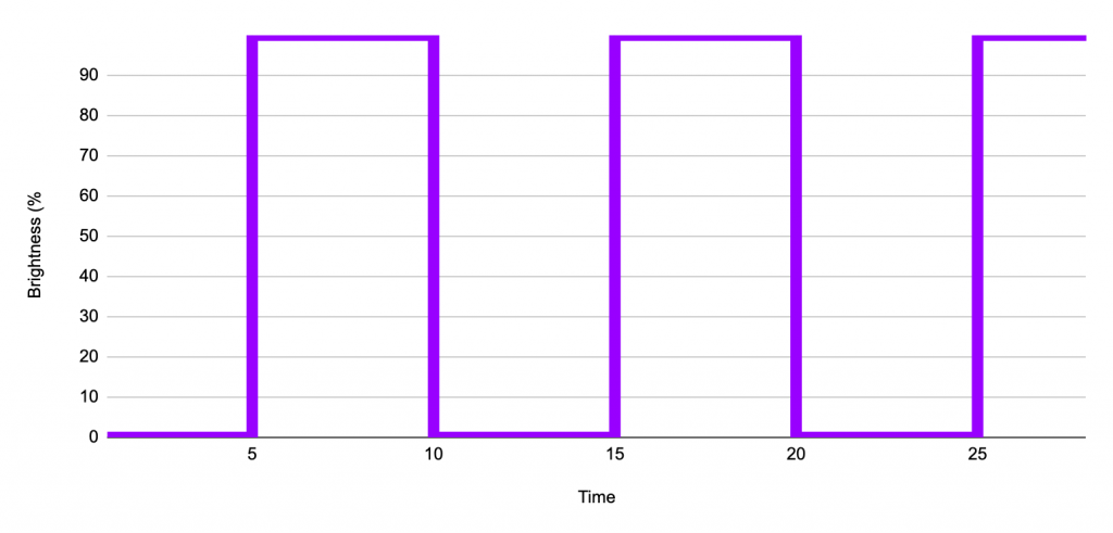
If we take our flashing lamp and then plot the cycle of on and off, it will look something like this. As you can see from the graph the lamp is transitioning from 0% brightness to 100% brightness and then back to 0%.
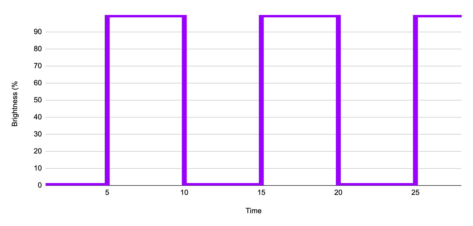
You should be able to see that this pattern is repeating every 10 units of time. Therefore from 0 to 10 we can see one complete iteration of this pattern and then afterwards the pattern just repeats over and over again.
The unique portion of the pattern from 0 to 10 units of time is called a cycle. The cycle repeats at between 10 and 20 units of time and begins again at 20 units and so on. The following graph shows a single on off cycle.

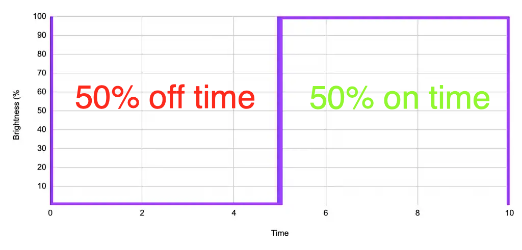
50 percent duty cycle
Now here is the clever bit, when the light is flashing very quickly or we can say that when the duty cycle is fast enough so that the eye cannot perceive the change in off to on and back to off.
The percentage of time that the light is on in each cycle is directly proportional to the perceived brightness.
If we switch the light on for 50% of the time and off for 50% of the time, the human eye will perceive the brightness as 50%, where the brightness is equal to the percentage of “on” time.
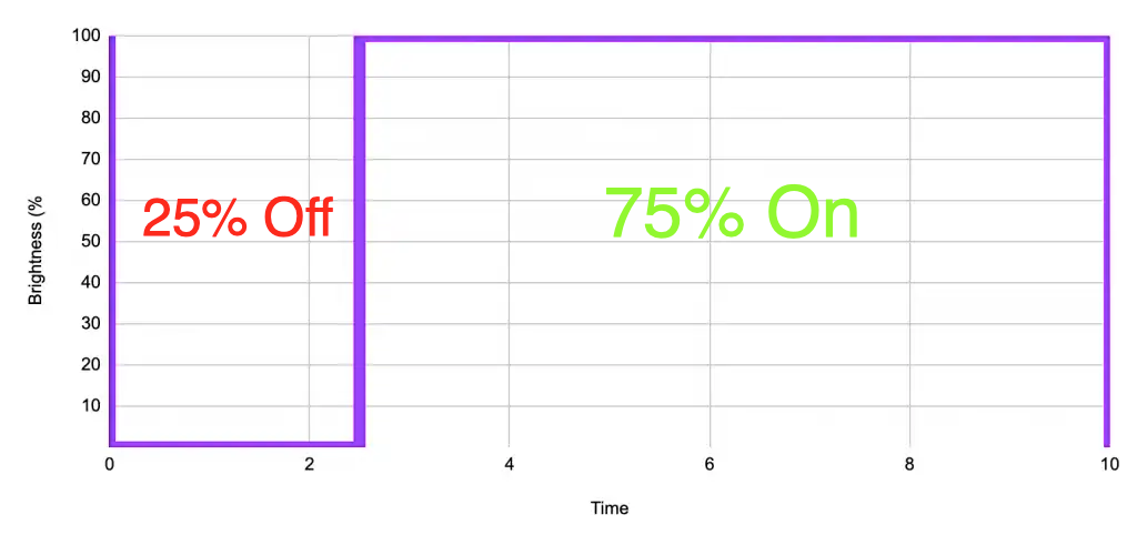
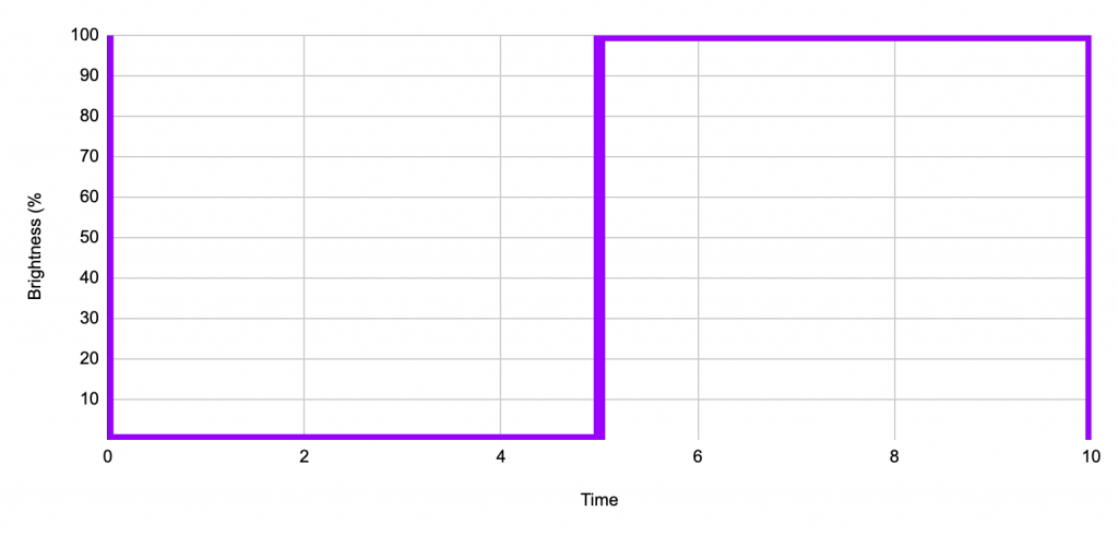
75 percent duty cycle
The ratio of time that the light is on compared with off is known as the duty cycle. If we are to illuminate our lamp for 75% of the time, we produce a duty cycle of 75%, which will also have a perceived brightness of 75%.
Pulse width modulation
As we are repeatedly sending an on and off signal to our light, we can say that we are continuously pulsing it. When we change the duty cycle we are changing, or modulating the width of the pulse.
This is where we get the terminology pulse width modulation. It means that we must modulate the pulse width in order to control the brightness. This is exactly how we can control the brightness of our LED.
What is the benefit of pulse width modulation?
When it comes to controlling the brightness of a light source, Pulse Width Modulation (PWM) offers numerous advantages:
- Efficient Light Control: PWM is an energy-efficient method for adjusting the brightness of a light. By rapidly turning the light source on and off at a specific duty cycle, the average power delivered to the light is effectively controlled. When the light is “on” during the ON time of the PWM cycle, it emits full brightness, and when it’s “off” during the OFF time, it consumes virtually no power. This results in higher efficiency compared to traditional dimming methods that dissipate excess energy as heat.
- Precise Brightness Adjustment: PWM allows for precise control over the brightness of the light. By varying the duty cycle, which represents the proportion of time the light is on during a complete cycle, the average intensity of the light can be finely adjusted. This level of precision is ideal for applications where accurate and smooth dimming is required, such as in ambient lighting, architectural lighting, or stage lighting.
- Smooth Dimming Performance: Due to the rapid switching of the light source, PWM provides smooth and flicker-free dimming. Traditional methods, like variable resistors (potentiometers), can cause flickering or uneven dimming due to mechanical limitations or voltage fluctuations. PWM eliminates these issues and ensures a consistent and visually pleasing dimming experience.
- Longer LED Lifespan: For LED lights, which are increasingly popular due to their energy efficiency and longevity, PWM dimming can extend their lifespan. Since LEDs are semiconductors, they are not affected by frequent on-off cycles as incandescent bulbs are. With PWM, LEDs experience fewer thermal stresses, leading to less degradation and longer operational life.
- Reduced Heat Generation: PWM minimizes heat generation in the light source. When the light is off during the PWM cycle, no power is dissipated as heat. This is especially advantageous for high-power lighting systems, as it reduces the need for elaborate heat sinks and cooling mechanisms.
- Compatibility with Digital Controls: PWM can be easily integrated into digital control systems. Microcontrollers, microprocessors, or programmable logic controllers (PLCs) can readily generate PWM signals, making it convenient to automate and integrate light control into broader smart lighting systems.
- Dynamic Lighting Effects: The precise control and smooth dimming capabilities of PWM open up possibilities for dynamic lighting effects, such as color changing, fading, and gradual transitions. This versatility is widely used in applications like stage lighting, mood lighting, and decorative illumination.
PWM is a highly effective and versatile technique for controlling the brightness of a light source. Its efficiency, precision, and ability to produce smooth dimming make it an excellent choice for various lighting applications.
How is a PWM Signal for Dimming Generated?
PWM signals are generated using electronic circuits, microcontrollers, or digital signal processors (DSPs). The specific method of PWM generation depends on the application and the complexity of the system. Here are some common techniques for generating PWM:
- Analog PWM Generation: In simple analog circuits, PWM can be generated using a 555 timer IC or similar analog components. The 555 timer IC can be configured as an astable multivibrator, which produces a square wave output. By adjusting the timing components (resistors and capacitors), the frequency and duty cycle of the PWM signal can be controlled.
- Microcontroller-based PWM Generation: Microcontrollers are widely used to generate PWM signals in modern electronic devices. Microcontrollers have built-in timers and hardware PWM modules that can be configured to generate PWM signals with high precision. The microcontroller’s software can control the duty cycle and frequency of the PWM signal, making it ideal for various applications, including motor control, LED dimming, and audio modulation.
- Digital Signal Processors (DSPs): DSPs are specialized microprocessors designed to perform signal processing tasks efficiently. DSPs can generate PWM signals with high precision and flexibility, making them suitable for sophisticated control systems and audio applications.
- FPGA (Field-Programmable Gate Array) Implementation: In more complex applications, PWM signals can be generated using FPGA technology. FPGAs are reconfigurable integrated circuits that allow designers to implement custom logic circuits, including PWM generators, tailored to specific requirements.
- Software-Based PWM Generation: In some cases, PWM can be generated purely in software without dedicated hardware support. In these situations, the microcontroller’s general-purpose I/O (GPIO) pins are used to manually toggle the output state at specific intervals, effectively creating a PWM signal. Although this method is less accurate and may consume more processing power, it can be useful in simple applications or situations where hardware PWM is not available.
Regardless of the specific method used, the fundamental principle of PWM generation involves toggling the output signal between two states (usually high and low) at a rapid rate.
The ratio of time spent in the high state (ON time) to the total period of one cycle (ON time + OFF time) determines the duty cycle, which, in turn, controls the average power or brightness of the controlled device.
By adjusting the duty cycle and frequency, different control levels and effects can be achieved, making PWM a versatile and widely used technique in various electronic and control applications.
Compensating for Perceived Brightness
You may already know from high-school electronics class that you can dim an incandescent bulb simply by altering the voltage. This is also how a simple domestic dimmer switch works.
Firstly we need to understand that an incandescent bulb is just a resistor sealed in a glass chamber containing an inert gas. The filament within the bulb has a low level of resistance, meaning it will dissipate a lot of power when we pass a current through it.
As the filament is made from a metal (usually tungsten) with a very high melting point it can glow white hot without melting. The inert gas provides an oxygen-free environment for the filament, also preventing it from burning up.
The current passed through the filament is dissipated as both heat and light. As you can imagine a lot of heat is produced, which is why this type of light is not so efficient. Most of the power creates heat and the remainder is given off as light from the bulb.
In order to control the brightness of the incandescent bulb we need to control the amount of power that it dissipates. This can be explained using Watt’s law, which says that the power dissipated is equal to the current multiplied by the voltage.
P = I x V
The problem here is that want to use voltage (v) to control our power (p) but we don’t know the value of current (I). Therefore we must substitute it using Ohm’s law, which says that voltage is equal to current multiplied by the voltage.
V = I x R
First we must rearrange this in terms of current (I).
I = V / R
Now we can replace current (I) in Watt’s law with the volts divided by resistance from our rearranged Ohm’s law equation.
P = (V / R) x V
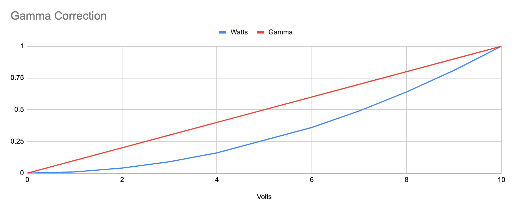
If we plot this as a chart using an arbitrary value of 100 ohms for the resistance, we can see that the plot is almost linear.
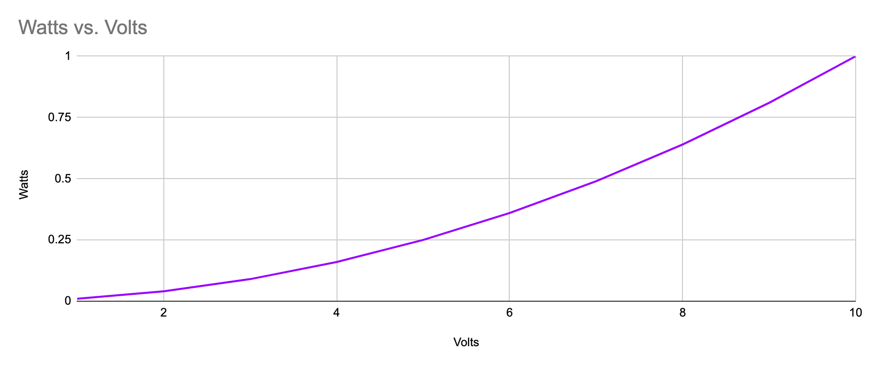
However the human eye does not have a linear response to an increase in brightness. We can compensate for this by applying a gamma correction of 2 to the original curve.
The resulting graph gives us the actual perceived brightness increase as the voltage increases. As you can see the “real world” perceived increase brightness is linear with respect to voltage.
Using PWM dimming is also non-linear. The human perception of brightness is not directly proportional to the amount of time a light is on during each cycle.
Instead, it follows a logarithmic response. As the duty cycle increases, the perceived brightness grows, but the relationship is not linear.
Here’s why LED PWM dimming is non-linear:
- Human Perception: The way our eyes perceive brightness is non-linear. Small changes in brightness at lower levels are more noticeable to our eyes than at higher levels. As a result, a linear increase in duty cycle may not result in a linear increase in perceived brightness.
- Relative Intensity: When the LED is on for a short time (low duty cycle), it appears less bright than when it is on for a longer time (high duty cycle). The difference in perceived brightness between the two states is not proportional to the difference in duty cycle.
- Electroluminescence: LEDs emit light due to electroluminescence, which is a non-linear process. The relationship between electrical current and light output in LEDs is not linear, and this contributes to the non-linear response of LED PWM dimming.
To achieve a linear dimming response with LED PWM, additional compensation or gamma correction can be applied. Gamma correction involves manipulating the duty cycle to account for the non-linear characteristics of human vision and LED brightness.
By carefully adjusting the PWM signal, it is possible to achieve a more linear relationship between duty cycle and perceived brightness.
What is LED PWM Dimming?
The acronym LED stands for light-emitting diode, therefore the humble LED is simply a diode that emits light. A diode is a semiconductor device and therefore its behaviour is non-linear.
We won’t dive to deep into the characteristics of LEDs but if you would like to understand this principle further, you should check out my tutorial about LEDs and resistors.
What this means is that it is not possible to reliably control a LED by simply adjusting the voltage, like we do with incandescent bulbs. Instead we must use the PWM technique to control the brightness.
There is also another huge benefit to using PWM to control the brightness of a LED. As the technique requires us to only turn the LED on and off, it lends itself perfectly to digital electronics.
Microcontrollers and PWM
In mostly all applications we will want to control our LED with a microcontroller or some kind of digital circuit.
As the whole principal of digital electronics is based on signals that are either only on or off, PWM is the perfect choice for implementing a microcontroller based LED dimming circuit.
How Does Binary Relate to PWM?
If we break digital electronics down to its most basic form, it consists only of an on and off signal, denoted by a 0 and 1 respectively. Therefore we can represent the on and off states of our PWM signal by 0s and 1s.
What is binary?
You will most likely be familiar with the decimal numbering system. It consists of the numbers 0 through to 9, so a total of 10 numbers.
Binary is also a numbering system like decimal, only it contains two numbers, 0 and 1.
There are other numbering systems found in computing such as octal, which contains 8 numbers.
You may have also heard of hexadecimal if you do any kind of programming. For example it is used to represent colours in web design and contains 16 numbers represented by the characters 0 to 9 and then A to F.
Converting number systems
It is possible to convert between all of these numbering systems using simples maths. What is of interest to us is the ability to convert between binary and decimal and it will become clear why later in the tutorial.
Firstly lets recap on some basic maths from the earlier days of school. A decimal number can be split into ones, tens, hundreds and thousands.
For example the number “232” contains 2 hundreds, 3 tens and 2 ones. We can write this in a table for clarity.
| Thousands | Hundreds | Tens | Ones |
|---|---|---|---|
| 0 | 2 | 3 | 2 |
Let’s look at another example, the number “2439.” It contains 2 thousands, 4 hundreds, 3 tens and 9 ones.
| Thousands | Hundreds | Tens | Ones |
|---|---|---|---|
| 5 | 4 | 3 | 9 |
So we can apply the same concept to binary in order to convert a decimal number to binary. All we need to do is replace the ones, tens and hundreds etc.
Let’s look at our first example of “232.” If we create a table with ones, twos, fours, eights and then continue to add columns, doubling this number for each, we can reproduce any decimal number using only 1s and 0s.
| 128 | 64 | 32 | 16 | 8 | 4 | 2 | 1 |
| 1 | 1 | 1 | 0 | 1 | 0 | 0 | 0 |
Adding each column value that contains a “1” will yield our “232” result:
128 + 64 + 32 + 8 = 232
Finally we can look at our second example for “2439.”
| 2048 | 1024 | 512 | 256 | 128 | 64 | 32 | 16 | 8 | 4 | 2 | 1 |
| 1 | 0 | 0 | 1 | 1 | 0 | 0 | 0 | 0 | 1 | 1 | 1 |
Again, adding each column value that contains a “1” will yield the decimal result:
2048 + 256 + 128 + 4 + 2 + 1 = 2439
Of course we don’t have to rely on this manual method to convert numbers, it simply serves as an explanation so that you understand how to convert the numbers.
You can use this handy online converter to do the maths for you!
What are binary bits?
The number of binary numbers that we can use in this system can also be referred to the number of “bits” that we have available.
If we take our first example of 232, you can see that 8 bits are required to represent this decimal number in binary:
| Bit 8 | Bit 7 | Bit 6 | Bit 5 | Bit 4 | Bit 3 | Bit 2 | Bit 1 |
| 128 | 64 | 32 | 16 | 8 | 4 | 2 | 1 |
| 1 | 1 | 1 | 0 | 1 | 0 | 0 | 0 |
We call the bit to the far left the most significant bit (MSB) and the bit to the far right the least significant bit (LSB).
The maximum number that we can represent with 8 bits is decimal “255” which we get if we add all column values. This gives us a total of 256 possible numbers when we also include zero.
To represent the number 2439 given in our second example, we need a total of 12 bits. Therefore the maximum decimal number that a digital system can represent is limited by the number of bits in the system.
In a computer the number of bits is usually limited by the number of physical signals that are available on the circuit board and within the processor.
What are binary bytes?
A byte is quite simply a group of 8 bits of data. Two bytes would therefore represent 16 bits of data, and so on.
To represent a number greater than 256 in an 8-bit system, we would need to use two bytes of data. For example if we wanted to represent “2439” in an 8-bit system, we would need to use two bytes of data.
"00001001" and "10000111"
If we combine the two bytes above into one string of binary, the decimal output will be 2439.
So what does this all mean and how does it relate to PWM?
In most cases we will be using some kind of digital system to control our PWM signal, whether it be for dimming an LED, controlling a servo or any one of the other PWM applications.
All digital systems rely on binary, therefore it is essential to understand how binary works in order to understand how a digital system can produce a PWM signal.
What is Digital Resolution?
Let’s say that we are using an 8-bit system to control a PWM signal. We know that the lowest value that can be represented with 8 bit binary is 0, which we can assign a value of 0% for the duty cycle.
We also know that the highest value that we can represent with 8 bit binary will be 255, which we can assign a value of 100% for the duty cycle.
In addition we also know that the total number of decimal numbers that we can represent in binary is 256 when we include the zero.
Therefore with our 8 bit system, we can have 256 steps of brightness. If we increase the number of bits and therefore increase the number of available decimal numbers, we can in turn increase the number of steps of brightness.
More steps of brightness we have, the more granular control we have over the brightness.
For example, if we were to produce a fading effect where an LED faded from off to on in 2 seconds, the fade would look smoother when using more steps of brightness.
If we were to use a 4-bit system, we could only have 16 steps in brightness as we can only represent 16 decimal numbers with 4 bits. This would not produce a very smooth fade!
An 8-bit system is usually thought of as a good compromise between cost and performance, although a 12-bit or even 16-bit system would give better results.
So the higher the number of bits, the better the resolution that we can achieve and the effect applies exponentially for each bit we add.
For example, an 8-bit system can represent up to 256 steps but a 16-bit system does not represent 512 steps, it represents 65,535 steps!
So why not choose always choose a higher number of bits?
It simply comes down to cost. Increasing the number of bits increases the cost of the microcontroller and often it makes sense to choose the minimum number of bits for the application in order to keep costs lower.
How to Calculate Digital Resolution
Let’s look at a simple calculation that we can use to convert a step number into a value of percentage that makes sense in terms of our duty cycle.
100 / total number of steps * step number
8-bit system
Let’s pick an arbitrary number of 200 for the step in an 8-bit system. We know the maximum number of steps is 256 so we can calculate the duty cycle for step 200.
100 / 256 * 200 = 78.125%
Now let’s calculate the percentage value for the next step, 201.
100 / 256 * 201 = 78.516%
We can see here that 1 step in an 8-bit system makes a 0.39% change to the PWM duty cycle. We can also calculate this directly.
100 / total number of steps
100 / 256 = 0.39%
12-bit system
Now let’s take a look at the resolution for a 12-bit system. We know that a 12-bit system can represent up to 4096 steps, so we can apply this to the formula above.
100 / 4096 = 0.024%
That is a huge difference! In a 12-bit system there are a little over 16 steps for every single step in an 8-bit system. This means a 12-bit system has a resolution 16 times finer than an 8-bit system.
This makes a very noticeable difference to how smoothly we can fade brightness. It also means we can reproduce many more colours using an RGB LED.
Which Resolution is Best for LED Dimming?
So you may be thinking why don’t we just use a system that has millions of bits for a near-infinite resolution?
The answer lies in the hardware limitation. For each “bit” in our system, there needs to be a wire inside our chip to represent the bit. It is just not feasible to cram this many wires inside a tiny little chip.
It is also more costly to produce a chip with more bits, therefore there is a tradeoff between cost and performance.
For many digital dimming systems an 8-bit resolution provides a good balance between cost and performance.
Most 8-bit microcontrollers provide the ability to implement a PWM system with more than 8-bits, however this can be at the expense of performance or resources available within the chip.
How to Implementing PWM LED Dimming
Some microcontrollers feature dedicated hardware to produce a PWM output that we can use for dimming. It is also possible to implement it with software and a general purpose IO pin (GPIO).
We will take a look at manually implementing an 8-bit system in order to gain an understanding of how it works.
PWM Cycle time
Another factor that we did not discuss yet is cycle time. This is the time that it takes our PWM to complete one cycle. Let’s go back to our graph from earlier and consider a unit for our time axis.
We can say that the unit of time for our graph is milliseconds. There are 1000 milliseconds in 1 second.
1ms = 0.001 seconds
PWM Frequency
We already know that one cycle of the PWM signal takes 10 units of time, therefore we can say that the cycle time for this PWM is 10ms.
The speed in which a PWM signal repeats over and over is usually expressed as frequency. Now that we know the cycle time, we can calculate the frequency (f).
f = 1 / cycle time in seconds
f = 1 / 0.01
f = 100 Hz
The frequency of the PWM signal in our example graph is 100 Hz, or we can say that the cycle repeats 100 times per second.
This is enough to produce the PWM effect but it is probably a little too slow and some flicker of the LED may be noticable. A better frequency to use would be something like 10,000 Hz, or we can say 10kHz.
We can rearrange our formula to calculate the required cycle time (t) in seconds from our given frequency.
t = 1 / frequency
t = 1 / 10,000
t = 0.0001
Our calculated cycle time is for a frequency of 10KHz is therefore 0.1ms. We can use this calculated time to implement our PWM system in a digital microcontroller.
Microcontroller Peripheral Timer
A common peripheral found within a microcontroller is a timer, you can think of it like a stopwatch. In our microcontroller code we can start and stop the timer. We can also read the current time and use it in our program.
The timer within a microcontroller is fundamentally a circuit within the chip that counts from zero up to its maximum value and then resets back to zero. It will continue to do this whilst it is enabled.
As the timer is a hardware peripheral, the number that it can count up to is determined by the number of bits used in its circuitry. For example an 8-bit timer can count from 0 to 255. A 16-bit timer can count from 0 to 4096.
Master clock
The time in which it takes to get from zero to its maximum value is linked to the master clock speed of the chip. For example a common clock speed used by the ATMega microcontrollers found on many Arduino boards is 16MHz, or 16,000,000 Hz.
Timer clock speed
We can change the settings in the programming on our chip so that our timer divides up the master clock speed, giving us a specific time that it will take for it to fully elapse to its maximum value.
Using our example from earlier, we will divide the master clock speed so that the time it takes our timer to fully elapse will be our desired PWM cycle time of 0.1 ms. We will use an 8-bit timer, which will give us an 8-bit PWM resolution.
PWM timer
Our timer will store its current value in a register within the microcontroller. This is simply a location within the memory of the microcontroller.
We also need to store our desired PWM value in another register location within the memory. We know this value first by starting with our desired duty cycle. Let’s pick an arbitrary value of 60% and convert it to an 8-bit number that represents the required step.
We can do this by rearranging the formula that converts between steps and duty cycle.
step = total number of steps * (duty cycle / 100)
step = 154
Now we need to convert this to a binary value. We could use the table method from earlier, but it will be quicker to use the handy converter.
154 = 10011010
Therefore to produce our PWM signal at one of the digital pins on the microcontroller we need to write a program that repeatedly compares the value of the timer register to the value in the PWM register.
We can say that if the timer value is lower than the PWM value, switch the digital pin on. If the timer value is higher than the PWM value, switch the digital pin off.
As the time continually elapses in the time specified by our cycle time calculation, the digital pin will be on for the length of time stored in our PWM value register.
This will create a loverly PWM signal to dim our LED to the desired value stored in the PWM register. We can then write a program to control the brightness of the LED simply by changing the value in the PWM register!
Conclusion
In this tutorial we have covered the complete theory of how PWM works and how it can be implemented into a digital system.
PWM is a superb way to accurately control the brightness of a LED and can be be easily implemented into the most basic digital systems.
I hope that you found this tutorial useful and congratulations if you made it to the end! Please let me know what you thought in the comments and feel free to ask any questions that you may have.
Next go check out my tutorial on LEDs and resistors for some further information about how LEDs work!
Article Updates
Aug 4th 2023 : Formatting updated, minor edits. Featured image updated. TOC added.
Article first published February 26th 2020.
Thanks so much for visiting my site! If this article helped you achieve your goal and you want to say thanks, you can now support my work by buying me a coffee. I promise I won't spend it on beer instead... 😏


Pingback: URL