
Most websites will just tell you to put a smart bulb in an existing fixture… but what if there is another way? What if your favorite lamp doesn’t take a traditional bulb?
In the first part of this article we looked at the inner workings of a lamp that utilises LED strip and covered some basic electronics theory in order to understand how it works.
In order to make a standard lamp in to a smart lamp, it must be connected to some kind of controller. Usually this will be a wireless device that connects to a smart home hub, app or software. Once connected, the on/off, brightness and colour functions of the lamp can be controlled by an external stimulus.
If we are using a basic lamp with standard bulb then we can simply add one of many different smart bulbs available. Another way would be just to use a smart plug, however this only adds on/off functionality.
It is becoming more common for manufacturers to use LED strips in light fixtures, therefore for this type of fixture we have the option to add a standard LED strip controller in order to make our lamp smart.
The second part of this article will focus on the controller and how we can add it to the lamp.
Table of Contents

Choosing a controller
I already have a controller in mind and I will explain why I would recommend it. My iteration of the controller is branded “MagicHome” and is readily available online.
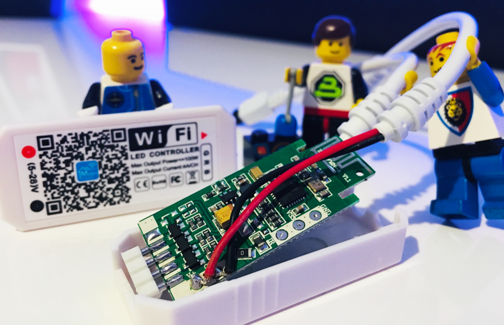
They are made in China but work very well, I have several of them installed in my home now. There are several key benefits to using this controller.
The software
The MagicHome app is actually pretty good, it is very easy to use and in my experience it worked well with minimal latency. If you didn’t want to go to the trouble of setting up a Home Assistant server, the standard firmware and app would give adequate results.
However for the smart home enthusiasts and folks looking for serious integration, this device is very easy to flash with Tasmota. Tas…what?
Tasmota is open source firmware that is compatible with devices that contain the ESP8266 chip found in many of the Chinese devices and other open source projects. The MagicHome controller uses the ESP chip, so we can easily reprogram it with Tasmota and integrate it into our Home Assistant system.
Cost effective
I don’t want to use the word ‘cheap,’ because the device is fairly well made albeit rather simple. It is one of many smart home devices to come out of China, making it very affordable and easy to purchase from places such as Amazon.
Personally I currently stick to the MagicHome or SmartLife branded products for my smart home. I know these devices predominantly use the ESP chip and therefore can be flashed with open source firmware and taken out of the cloud.
I tend to avoid using the bundled apps for reasons other than performance, but for folks who do not want to have to reprogram their devices, I would say go right ahead and use them.
Easy to modify
This is only relevant to the folks who wish to bring their device out of the cloud by flashing Tasmota or another alternative firmware.
I have flashed quite a number of these MagicHome controllers now and the case is easy to open without causing any damage. It is possible to simply pry them open from the LED connector end.
They also have labelled test points on the bottom side of the circuit, making it very easy to connect a programmer.
Compatible with 12 volt LED strip
In the previous article we discovered that our LED strip was rated at 12V, which is a very common voltage for this application. We also encountered an unusual output voltage from the transformer and determined that no additional voltage regulation was used.
We made an assumption that the forward current for our white LEDs was the standard 60mA. We also calculated that it would require 18V in order to run the LEDs at their maximum brightness, which is the given upper limit of what the power supply can produce.
With our calculations in mind and the fact that the strip is rated by the manufacturer for 12V, our MagicHome controller should work well. It might not be quite as bright but I am confident it will be adequate.
Installing the controller
It is finally time to install the controller! For this project I selected the RGBW derivative of the MagicHome controllers. I will only be using one of the four available channels as this lamp only has white LEDs.
It does not matter which of the RGBW channels we use as later we will define it as a single colour device in Tasmota.
I have seen white only derivatives of this type of controller, however they seem harder to find and there is negligible cost saving. Therefore I decided to repurpose one of the ubiquitous RGBW iterations of the board.
Inside the controller
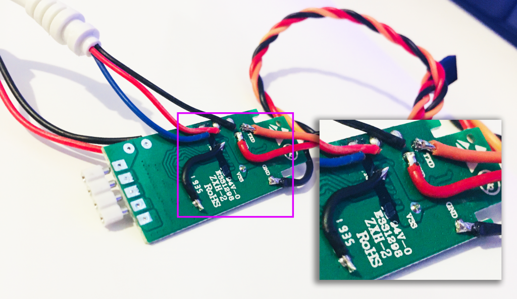
I have disassembled a few of these controllers to flash them but never really looked at them in any greater detail.
Looking at the area where the power wires are soldered we can see that the positive wire delivers current to all of the LEDs globally and the individual RGBW channels sink the current to ground.
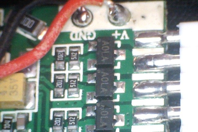
Looking under the microscope we can see some SOT-23 packages, I cannot find anything conclusive from the marking “A0LA,” however these will almost certainly be MOSFETs that sink the current from each channel.
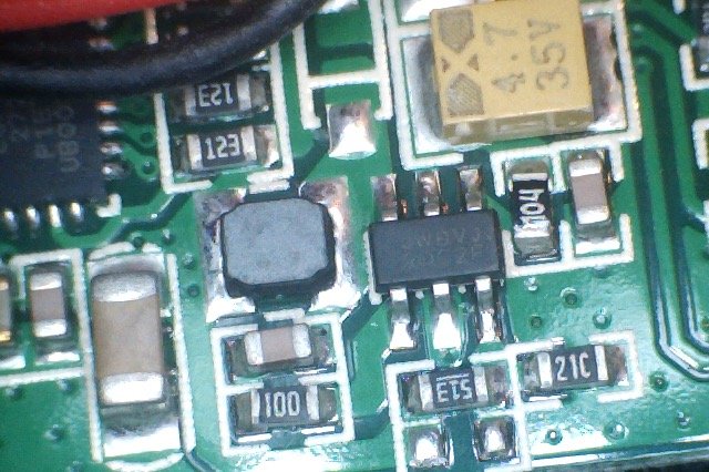
The other area of interest is this little group of components. The purpose of this part of the circuit is to provide a 3.3V supply to the rest of the circuit. It is a switching regulator made up of a controller IC, inductor and some other passives.
It is very hard to read the marking on the top of the IC, so no chance of finding the datasheet! This is frustrating as I cannot be sure if it is acceptable to supply this chip with 18V from the lamps power supply.
I thought I better just check the output from the original power supply. Wowzers! The meter was reading 21 volts! So we are two volts above the maximum given voltage on the label of the power supply. Good job we checked!
Choosing a suitable power supply
There is no way I am going to use this power supply with the MagicHome controller, it is almost double the expected voltage. A few volts would have probably been ok and would have been absorbed by the switching regulator, but this is too much.
I have a 12V supply that I can use with the MagicHome Controller for now. If I decide to switch back to the original supply, I will probably put a 12V linear voltage regulator in between it and the controller.
Wiring
In the first part of this post we discovered that this particular lamp has a 2-pin DIN connector between the power supply and foot switch. This saves us having to cut the wire, although this would have been no problem.
Disclaimer: Caution must be taken, your lamp may be powered from mains voltage and therefore you must NOT attempt to modify your lamp unless you are absolutely confident you understand what you are doing. You may also cause damage to your lamp, so proceed at your own risk.
I may be stating the obvious here but I must say that you SHOULD NOT cut the wire whilst the lamp is plugged in.
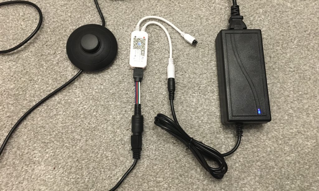
So long as we have a break between the power supply and LED strip, we can install our LED controller. The 12V supply I have for the MagicHome controller plugs straight in, it is the one I keep on the bench for when I need a power supply for flashing them.
Next I need an adapter lead so that I can connect the male 2-pin DIN plug on the lamp to the controller. I have a spare connector that I cut from another piece of LED strip, all I needed to do was attach a 2-pin DIN plug on to the other end.
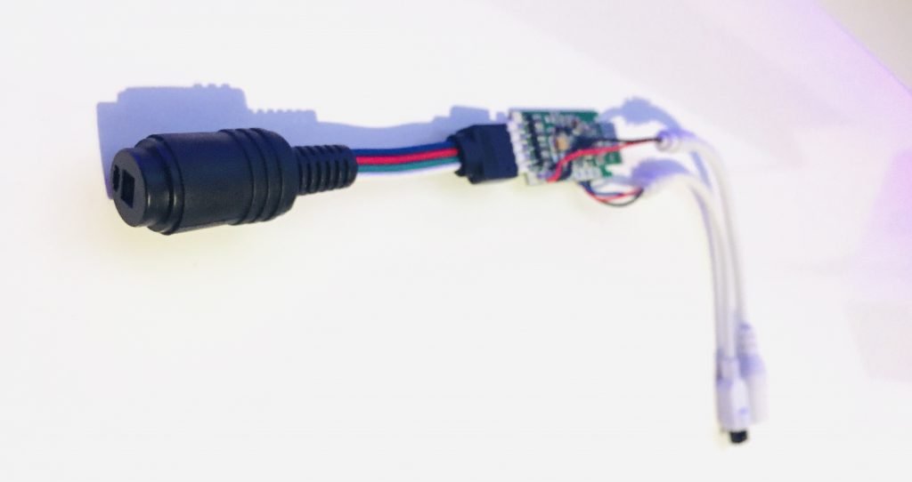
I have wired the white lead to the supply voltage pin on the controller and positive terminal of the DIN plug. The negative pin of the DIN plug is connected to the red channel.
We should not think of this as the red channel, but simply as channel 1. Tasmota can assign any channel to any PWM function, so we can configure the device as a single colour and use channel 1 (the “red” channel) to control the strip. We could use any of the channels, I would recommend choosing whatever channel is easiest to physically connect.
If you wanted to use the MagicHome controller with the original app it should work fine too. For example if you connect the white strip to the red channel, the lamp will just switch off if you select green or blue.
That’s the hardware complete! The 12V power supply is connected to the MagicHome controller and the controller is connect to the lamp with the adapter lead.
If you are going to use the app that came with your controller, go ahead and follow the process of adding the device as normal and enjoy your new smart lamp!
If you wish to do a more advanced configuration then please continue on to the next section where we will configure Tasmota and get our new lamp up and running in Home Assistant.
Configure Tasmota
In this section we will look at the Tasmota setup. My controller is already flashed with the latest version of Tasmota and ready for configuration. If you need to flash your device first, I have a detailed guide on how to do this here.
I also have a detailed guide that covers how to set up Tasmota with Home Assistant using MQTT auto discovery if you need to get your device connected to Home Assistant.
We will focus on the device configuration here, as it is not standard. We are using an RGBW controller but want it to appear as a device with a single colour.
The first thing I did was head over to the Blakadder template repository to locate the device. There is already a MagicHome RGBW template in the repository. In order to use this template, go to the configuration menu and then configure other.
Here we can enter the template, just copy and paste it from the template repository.
{"NAME":"ESP-IR-B-v2.3","GPIO":[0,0,51,0,0,38,0,0,37,39,0,40,0],"FLAG":0,"BASE":18}
Make sure you tick the checkbox next to activate and enter a friendly name for your lamp. Click save and wait for Tasmota to reboot.
Once Tasmota has rebooted you should be presented with the standard RGBW control. We can now switch on the lamp and set it to white so all four channels are on.
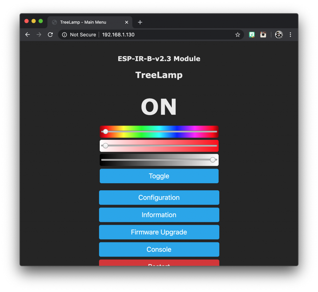
We don’t know which channel is connected yet but if all channels are all on then lamp should turn on. In may case it worked and it was brighter than I expected!
Custom Tasmota template
So how to we convert it into a single colour? We need to modify the configuration template. The part we are interested in is the string of numbers.
[0,0,51,0,0,38,0,0,37,39,0,40,0]
Each number represents a GPIO pin on the ESP chip, where the first number is GPIO0.
Note that GPIO6, 7, 8, 11 are reserved for other functions and are unavailable. The template represents GPIO0, 1, 2, 3, 4, 5, 9, 10, 12, 13, 14, 15 and 16.
The value of the number represents a component within Tasmota. You can see a full list of components in the documentation.
The first number in our template is set to zero, this value means the pin is unused, therefore GPI0 is not used. The second number is also zero, therefore GPIO1 is not used either.
The third number us set to ’51’ which is the component IRrecv. This means that GPIO2 must be connected to the IR LED, used for the MagicHome remote.
The other numbers are 37, 38, 39 and 40. These represent the four channels that control the LEDs, R, B, G and W. They are called PWM channels, which stands for pulse-width modulation. This is the technique used to control the LED brightness.
We have our white LED strip within the lamp connected to one of these PWM channels, but we do not know which one. In order to find out we can use a process of trial and error.
The method I used to find out was to disable all but one of the channels sequentially until I found the one that worked. This is done by setting all but one of the GPIOs to the component 0. When we find the template that works, we will know which GPIO pin is correct.
[0,0,51,0,0,38,0,0,0,0,0,0,0]
[0,0,51,0,0,0,0,0,37,0,0,0,0]
[0,0,51,0,0,0,0,0,0,39,0,0,0]
[0,0,51,0,0,0,0,0,0,0,0,40,0]
In my case I found the second of these templates to work, this means that I have my lamp connected to GPIO12.
The component specified for GPIO12 in the original template is ’37’ and it corresponds to PWM1. In order for Tasmota to configure itself as a single colour device, it must only have PWM1 configured.
If we wanted to use any of the other channels we would need to change the component to 37 in order to set that channel as PWM1. For single colour we should only have PWM1 configured.
Now we have GPIO12 configured as component 37, which is PWM1. We can leave component 51 intact for the IR receiver. This makes our final custom template.
{"NAME":"Siytek-MagicH","GPIO":[0,0,51,0,0,0,0,0,37,0,0,0,0],"FLAG":0,"BASE":18}
Once Tasmota has rebooted we find that it now presents us with the single colour control!
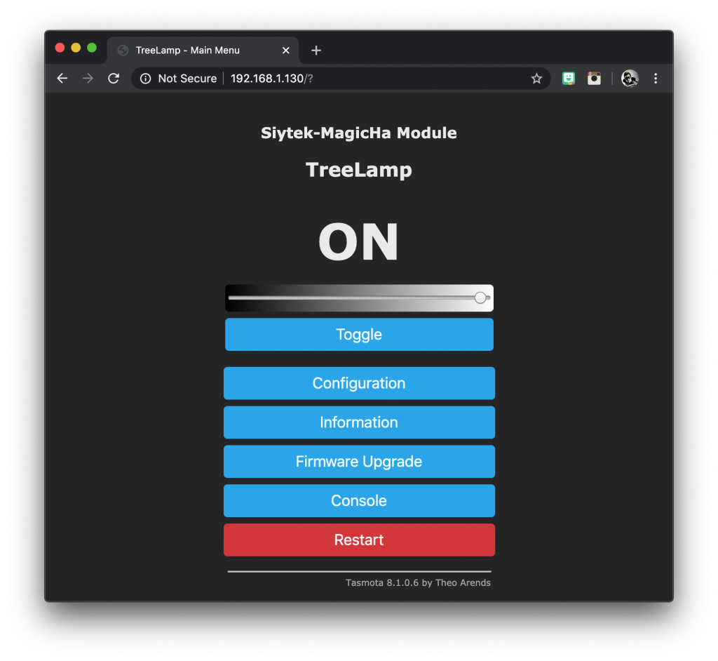
Now the lamp is working! We have successfully converted this standard lamp into a super-smart lamp, controlled by Tasmota. Now we can integrate it into Home Assistant.
I hope that you found plenty of useful information in this Tutorial and a big thanks if you took the time to read both articles. Please take some time to check out some of my other cool tutorials!
Thanks so much for visiting my site! If this article helped you achieve your goal and you want to say thanks, you can now support my work by buying me a coffee. I promise I won't spend it on beer instead... 😏


