
One of the easiest ways to make a temperature sensor for Home Assistant is to connect either a DHT11 or DHT22 temperature and humidity sensor to a Wemos D1 Mini. Best of all it will only cost you around the price of a beer!
If you are looking for the complete thermostat system, I have an epic post on how to make a DIY thermostat that uses these sensors. It is definitely worth checking out!
If you want to connect your home heating and/or cooling system to Home Assistant without spending a fortune on installing a closed source thermostat, you are going to need some way of measuring the temperature in your house.
The great thing about this solution is you can make many of them and detect the temperature in many different places. In a future project I plan to hide one inside a smart lamp.
In fact there are many possibilities for installing them inside other smart devices or generally hiding them. Personally I place great importance on the level of stealth that my smart home devices have!
Table of Contents
Requirements
This sensor is very easy to build and only requires a few parts. Depending on the format that you buy the modules, some additional assembly may be required.
In this article I will explain how to build the sensor in the easiest possible way. However I will include the tools that you may need depending on how you wish to build your sensor. The required parts are as follows.
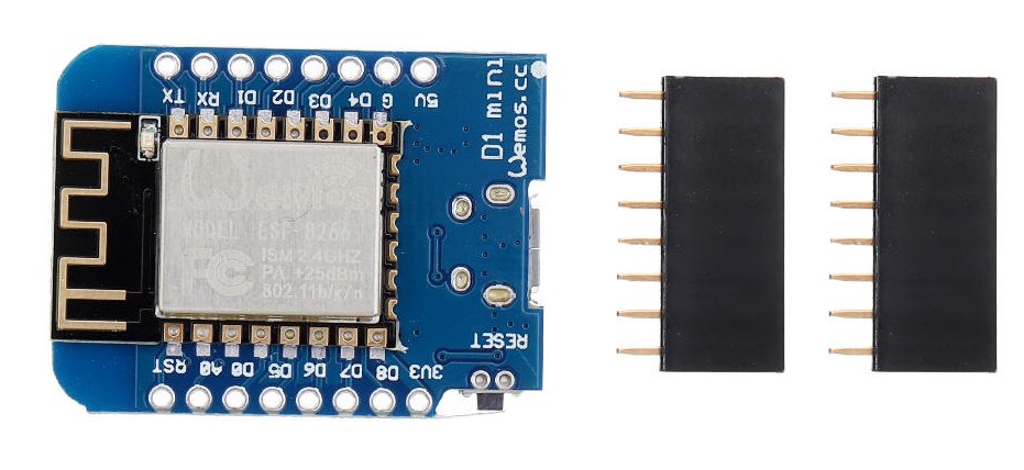
- A Wemos D1 Mini
- A DHT11 or DHT22 temperature/humidity sensor
- Micro USB cable
- Soldering iron
- Solder
If you purchase your DHT11/22 as a shield module, you can just plug it in to the D1 Mini, although you will probably have to solder the header terminals on to the board. If you want to avoid soldering, you can try to find a supplier selling the shield with a pre-soldered header.
Alternatively you can buy the sensor as a component, giving you more freedom with the installation. If you choose this route you will need the following.
- Some project wire or an old RC servo lead
- A 10k resistor
- A 0.1uF capacitor
Build the module
It is likely that your D1 Mini module came without the headers attached. If you are using a standalone DHT11/22, you can solder the wires directly to the board or solder the male header and use a header plug.
Tip: you can recycle an old RC servo lead if you need a lead that is compatible with male pin header. They usually have three wires that are positioned to fit on to Vcc, GND and D4 of the D1 Mini module.

Wiring
The DHT11 and DHT22 have four physical pins, however only three of them are used. We need to supply power and ground, the third pin is for 1-wire communication and it is used to fetch the data from the sensor.
- Vcc = 3.3 or 5 volts
- Data
- Not connected
- Ground
The data pin needs a pull-up resistor in order to hold it at Vcc. When the D1 mini wants to communicate with the sensor, it will transmit the data by pulling this pin low.
We will also add a capacitor across the positive and negative terminal in order to ensure the supply voltage remains stable.
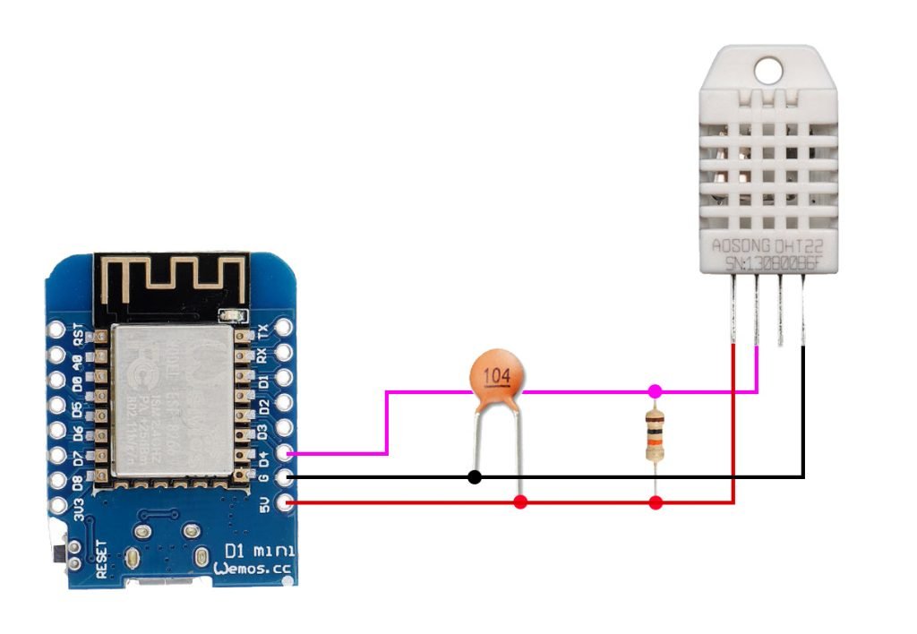
We will connect the sensor to the D4 pin of the D1 Mini as this is the pin the shield uses. However you can use a different digital pin if you like.
The sensor can be run from either 3.3V or 5V so you can choose which is best suited to your build.
DHT11/22 Shield
If you have a DHT11/22 sensor shield, I would recommend using the female header with the shorter leads but you can choose to configure it differently if you prefer.
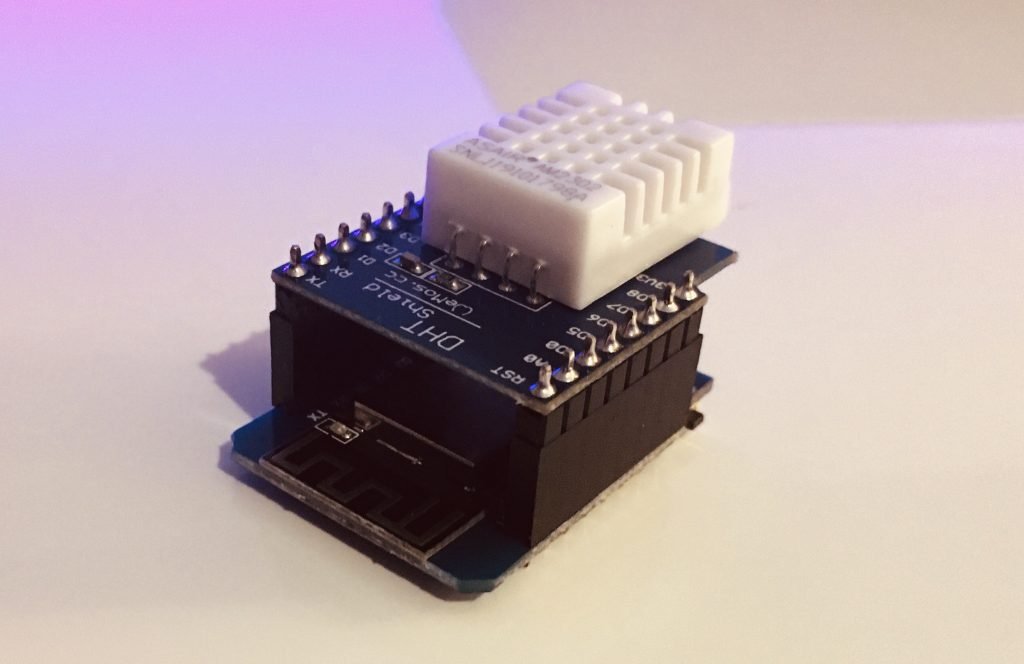
You will also need to solder the male headers to the DHT11/22 module. Make sure you solder them both to the correct side! With the DHT11/22 on top the male header should point downwards. On the D1 Mini the female header should protrude upwards on the same side as the WiFi chip.
Once you have finished the soldering, you can plug the shield in to the D1 Mini. Our completed module will look like this.
Flash Tasmota
Now that we have our module wired and built we can configure the software. We will be using the Tasmota firmware.
The D1 Mini has a built-in USB to serial interface so it is very easy to load the Tasmota firmware. Go ahead and connect your D1 Mini to your computer with a USB cable.
Tip: You can power your D1 Mini from any USB port. The temperature sensors in my house are powered from recycled iPhone chargers.
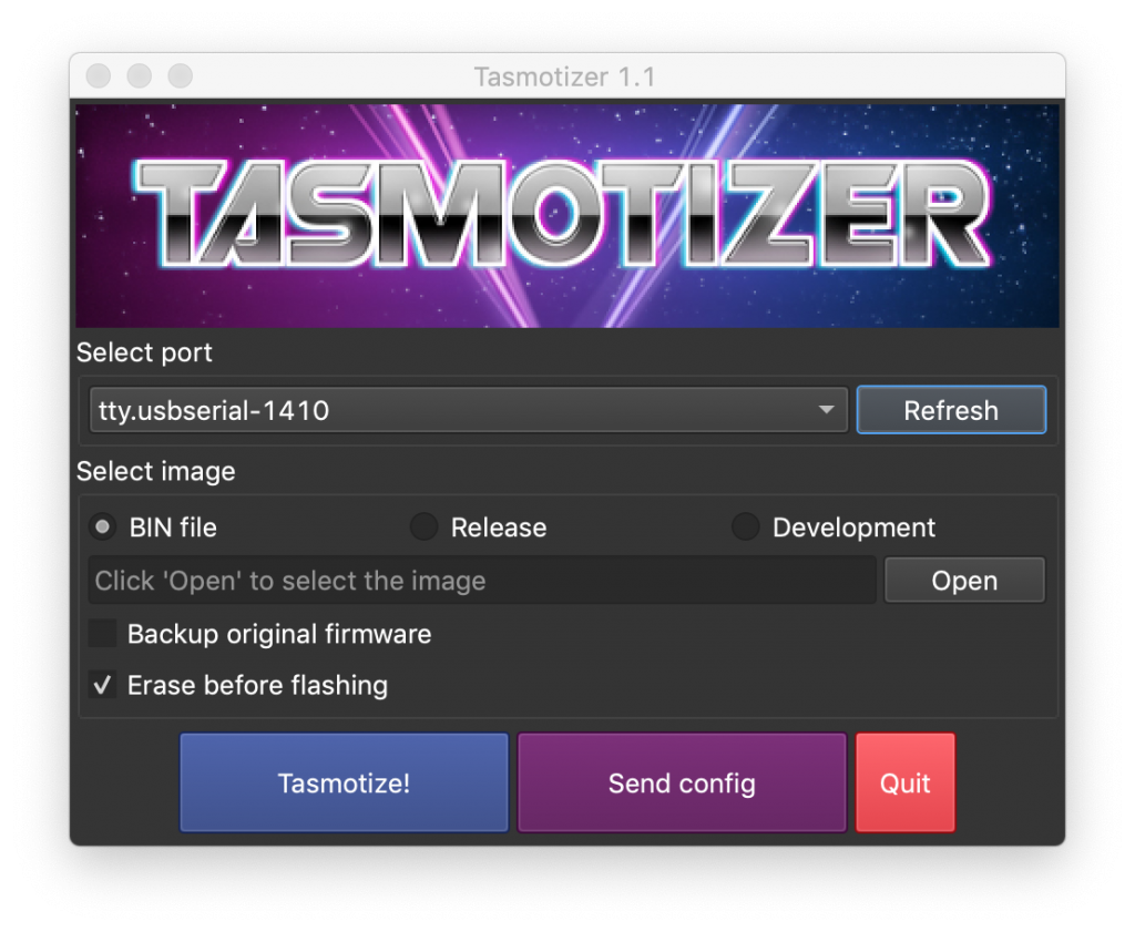
Use Tasmotizer
The easiest way to flash the device is by using the Tasmotizer software. It is compatible with Windows, Mac and Linux. If you need to flash Tasmota I would recommend following my complete guide on how to use Tasmotizer.
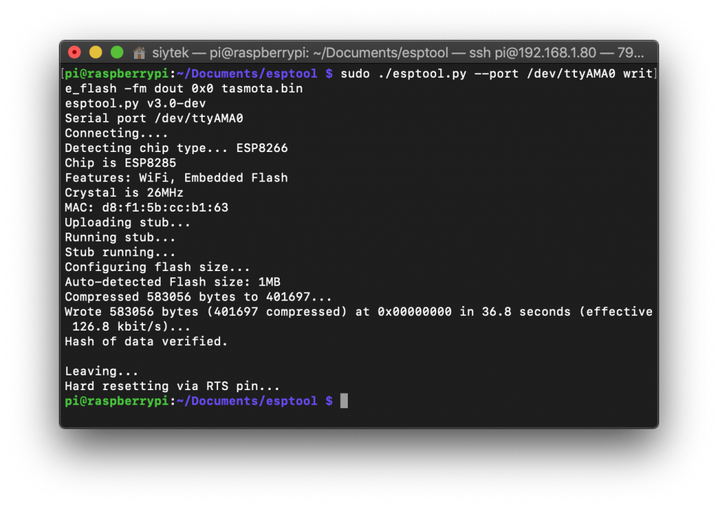
Mac/Linux Terminal
Alternatively if you are using a headless machine for flashing, or if you are using Mac/Linux desktop and you just want to feel like a hacker, you can follow this guide on how to flash the D1 Mini with terminal.
Configure Tasmota
Once you have flashed Tasmota to your D1 Mini you will need to connect Tasmota to your WiFi router and then find the IP address so that you can access the main menu. All of the steps for basic configuration are available in the latter part of this guide.
Once you have connected Tasmota to your router and can access the main menu, we can configure the device specifically to function as a temperature and humidity sensor.
From the main menu go ahead and click configuration followed by configure module. You will be presented with the module configuration menu.
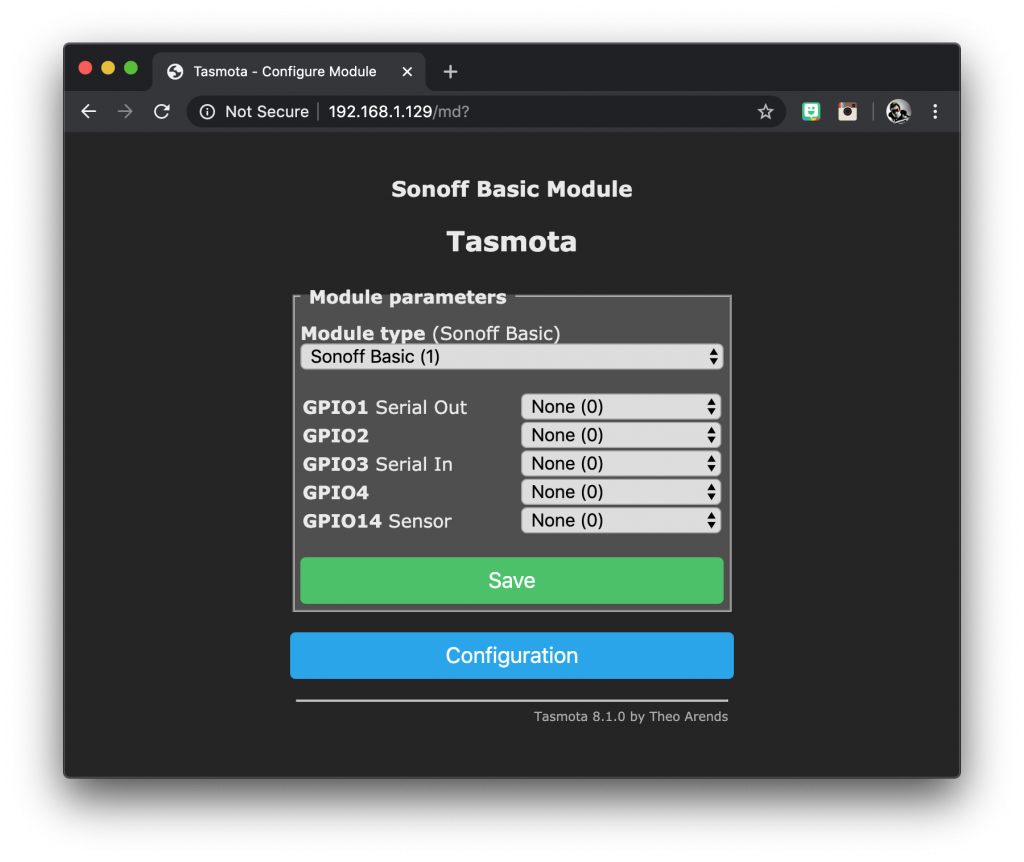
In the drop down menu under module type, you need to select the device generic (18). This allows us to configure our D1 Mini manufally. Click save and wait for Tasmota to reboot back to the main menu.
Once Tasmota has rebooted, go back to the configure module menu. You should see that all of the GPIOs are now available. We can select the function of each pin of the D1 Mini in the drop down menus.
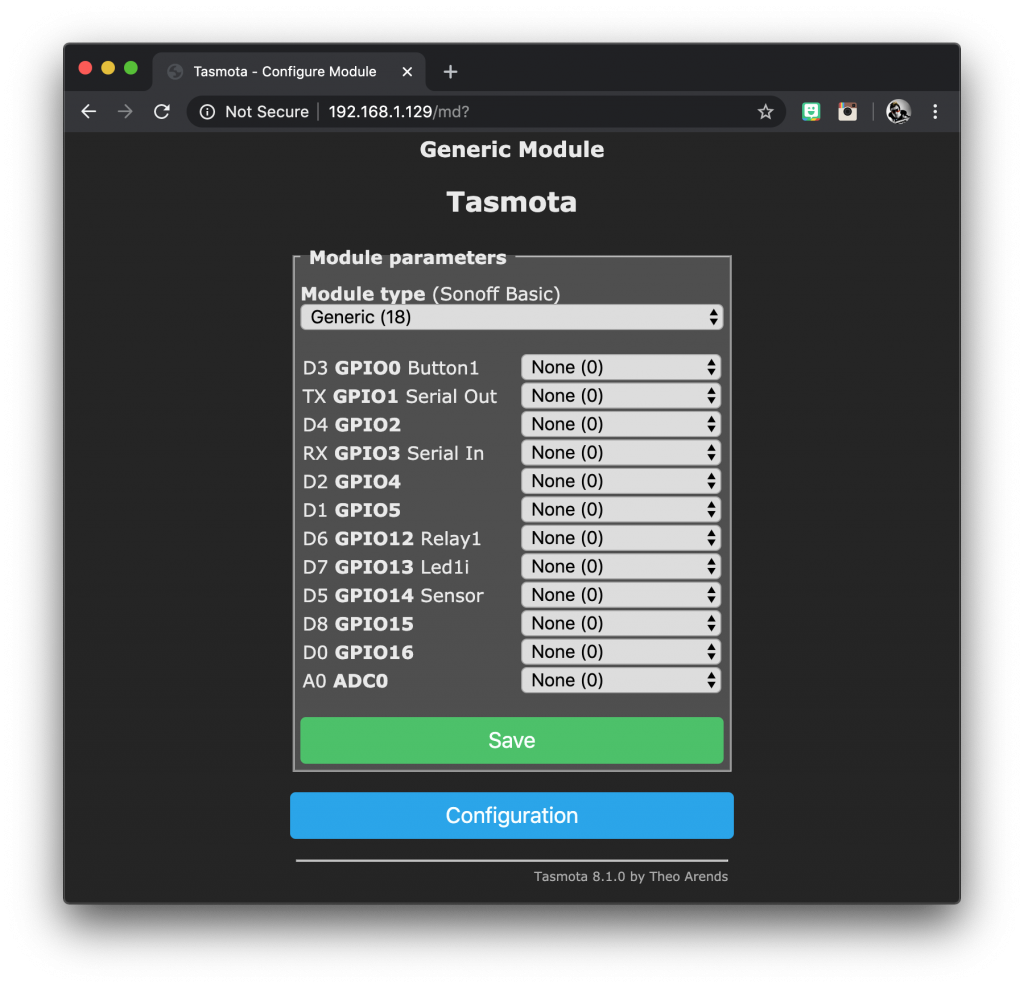
Next we need to select the DHT11/22 sensor in the drop down menu for D4. If you have wired the sensor to a different pin, you should choose the drop down menu for the pin that you have selected.
At the time of writing there is an option in the drop down menu for DHT11, however there is not an option for the DHT22. This had me stumped for a while!
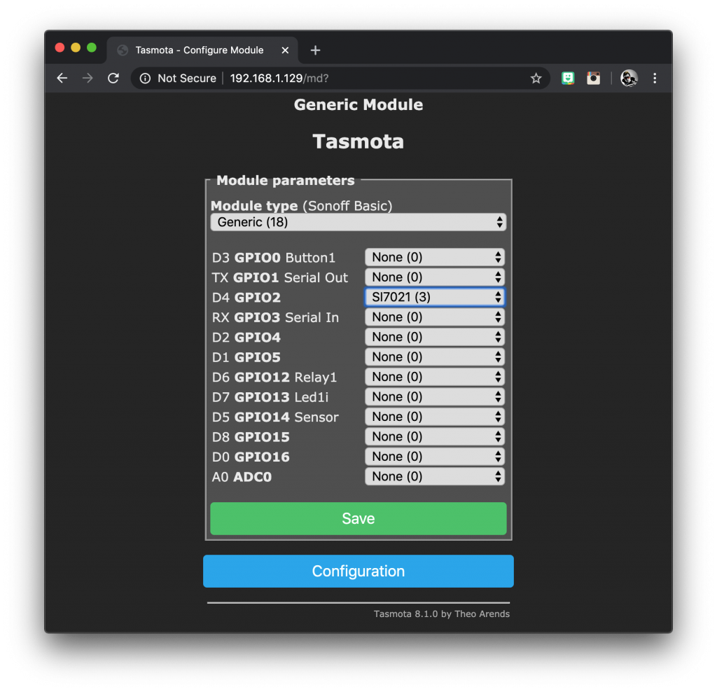
If you are using the DHT11 then you can go ahead and choose DHT11 (1) from the drop down menu.
If you are using the DHT22 sensor, you need to select SI7021 (3) from the menu as it uses the same 1-wire protocol.
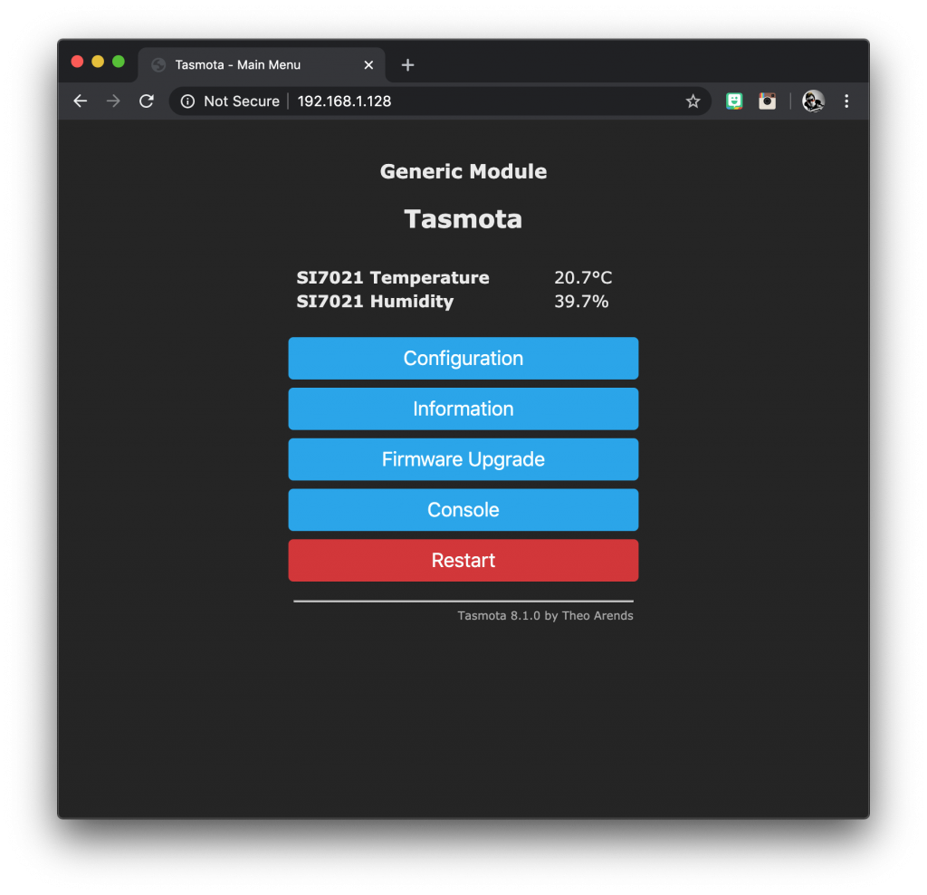
Click save and wait for Tasmota to reboot. After the reboot you should now be able to see the temperature and humidity readings on the main menu!
The next step is to configure MQTT and connect your device to Home Assistant, so go ahead and check out my tutorial on how to configure Tasmota to auto discover in Home Assistant using MQTT.
If you already know how to configure your device, definitely go check out my ultimate guide to making a DIY thermostat, it is the perfect application for these sensors.
I hope that this tutorial was helpful and thanks for reading! Please check out some of my other cool tutorials!
Thanks so much for visiting my site! If this article helped you achieve your goal and you want to say thanks, you can now support my work by buying me a coffee. I promise I won't spend it on beer instead... 😏


Hi, Very nice article however some pictures seems to be missing (in particular the wiring diagram)
Is it possible to have it please ?
Thanks in advance,
Cheers
Hi Julien, not sure why you could not see the images as they are not missing, perhaps a problem with the site cache somewhere that I need to look at. Anyway, you should be able to see the wiring diagram here, hope it helps! 🙂
https://siytek.com/wp-content/uploads/2020/02/DHT22-wiring-1024×708.jpg