With the Arduino ESP8266 library it is possible to get your device to function in both access point (AP) and station (STA) modes simultaneously.
In this article you will learn how to build a simple Arduino project that will get the ESP8266 to function in both AP and STA modes.
If you are primarily interested in access point (AP) mode, you can find a detailed tutorial here that covers AP mode along with handling clients using a simple web server example.
In this tutorial we will expand on the previous tutorial describing how to connect an ESP8266 device to a WiFi network.
As before I will be using a Wemos D1 Mini for the example, however you can use any ESP8266 device that supports the Arduino ESP8266 core.
Prerequisite
You will need to have the Arduino IDE installed and configured to flash ESP8266 devices. You will also need an ESP8266-based board, as this will not work with a standard Arduino board.
I would recommend the Wemos D1 Mini due to its compact size and simplicity. It also costs surprisingly little on Amazon, check the latest prices here.
If you are new to the ESP8266 and have not yet programmed it with Arduino, I would recommend that you first read my tutorial on how to configure the Arduino IDE for ESP8266.
What is ESP STA and AP mode?
ESP devices, such as the ESP8266 or ESP32, can operate in different modes depending on their role in a network.
What is STA mode in ESP8266?
In STA mode, the ESP device connects to an existing Wi-Fi network as a client. It behaves similarly to other devices like smartphones or laptops, allowing it to join an established network and communicate with other devices on that network. In this mode, the ESP device can access the internet or interact with other devices connected to the same network.
What is AP mode in ESP8266?
In AP mode, the ESP device functions as a Wi-Fi access point, creating its own network. Other devices, such as smartphones or computers, can connect to this network and communicate directly with the ESP device. This mode is useful when you want the ESP device to act as a central hub, allowing other devices to connect to it and exchange data.
Combining STA and AP Modes
By combining both STA and AP modes, you can create versatile projects where the ESP device connects to an existing network as a client (STA) while simultaneously hosting its own network for other devices to connect to (AP).
This allows for scenarios where the ESP device can act as an intermediary between different networks or facilitate direct communication between devices.
How To Configure ESP8266 for STA Mode
In the previous tutorial we covered how to connect an ESP8266 device to WiFi in station (STA) mode. In this mode the ESP8266 connects to the router as a client.
I won’t cover STA mode in full as I already covered it in the aforementioned tutorial. Therefore we will just take the code from the previous tutorial and begin by adding it to a new project. We will then add AP mode so that the ESP8266 functions in both AP and STA modes.
Ideally you should at least read through the WiFi section of the previous tutorial. However if you wish to skip over it, you can just start by creating a new project in the Arduino IDE and add the following code:
#include <ESP8266WiFi.h>

// Set WiFi credentials
#define WIFI_SSID "YOUR WIFI NETWORK SSID"
#define WIFI_PASS "YOUR WIFI PASSWORD"

void setup() {
  // Setup serial port
  Serial.begin(115200);
  Serial.println();

  // Begin WiFi
  WiFi.begin(WIFI_SSID, WIFI_PASS);

  // Connecting to WiFi...
  Serial.print("Connecting to ");
  Serial.print(WIFI_SSID);
  // Loop continuously while WiFi is not connected
  while (WiFi.status() != WL_CONNECTED)
  {
    delay(100);
    Serial.print(".");
  }

  // Connected to WiFi
  Serial.println();
  Serial.print("Connected! IP address: ");
  Serial.println(WiFi.localIP());

}

void loop() {
  // put your main code here, to run repeatedly:

}
How To Combine AP Mode and STA Mode on ESP8266
This project will connect your ESP8266 device to a WiFi network called WIFI_SSID using the password WIFI_PASS.
We can expand on the existing code in order to make our ESP8266 device also appear as an access point.
Add AP credentials
First we will define an SSID and password for our access point (AP). These credentials are separate from the credentials we use to connect to the router with STA mode, therefore we will define two new constants:
// Set AP credentials
#define AP_SSID "ESP8266"
#define AP_PASS "magicword"
Add the lines to your project and change the values to any values that you wish to use as the network name (SSID) and password for the AP.
Begin the Access Point
After the code that starts the serial port, found in the setup function, add the following line to start the access point:
  // Begin Access Point
  WiFi.softAP(AP_SSID, AP_PASS);
The function call WiFi.softAP(AP_SSID, AP_PASS) initiates Access Point (AP) mode on an ESP device:
WiFi: This refers to the Wi-Fi library that provides functions and methods to interact with Wi-Fi networks on the ESP device.softAP: It’s a function from the WiFi library used to set up an Access Point.AP_SSID: This is a variable representing the name (SSID) of the Wi-Fi network that will be created by the ESP device. You can replace it with a desired name, such as “MyESPAPNetwork.”AP_PASS: This variable represents the password required to connect to the Wi-Fi network created by the ESP device. You can replace it with a password of your choice, such as “MyPassword123.”
When this line of code is executed, the ESP device will start operating in Access Point (AP) mode. It will create its own Wi-Fi network with the specified SSID and password.
Print to the serial console
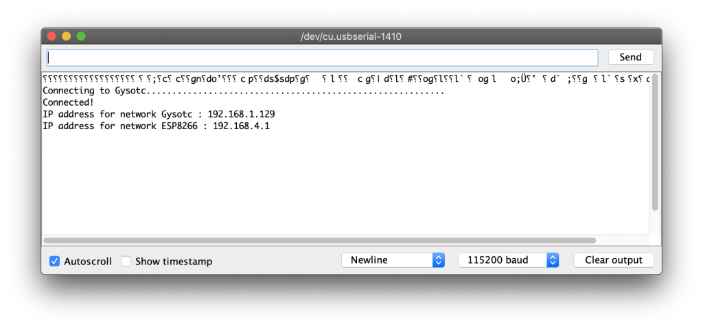
Next, we will add some additional commands that print additional information about the access point to the serial terminal. These are the details that you can use to connect to the access point.
  // Connected to WiFi
  Serial.println();
  Serial.println("Connected!");
  Serial.print("IP address for network ");
  Serial.print(WIFI_SSID);
  Serial.print(" : ");
  Serial.println(WiFi.localIP());
  Serial.print("IP address for network ");
  Serial.print(AP_SSID);
  Serial.print(" : ");
  Serial.print(WiFi.softAPIP());
That’s it! Now you can upload the sketch to the ESP8266 open the serial terminal. You should see confirmation that you have successfully connected. Your STA and AP IP addresses will also be displayed.
Completed Code for AP and STA Mode
The following code is the complete code for the AP and STA mode project:
#include <ESP8266WiFi.h>


// Set WiFi credentials
#define WIFI_SSID "YOUR WIFI NETWORK SSID"
#define WIFI_PASS "YOUR WIFI PASSWORD"

// Set AP credentials
#define AP_SSID "ESP8266"
#define AP_PASS "magicword"

void setup()
{
  // Setup serial port
  Serial.begin(115200);
  Serial.println();

  // Begin Access Point
  WiFi.mode(WIFI_AP_STA);
  WiFi.softAP(AP_SSID, AP_PASS);

  // Begin WiFi
  WiFi.begin(WIFI_SSID, WIFI_PASS);

  // Connecting to WiFi...
  Serial.print("Connecting to ");
  Serial.print(WIFI_SSID);
  while (WiFi.status() != WL_CONNECTED)
  {
    delay(100);
    Serial.print(".");
  }

  // Connected to WiFi
  Serial.println();
  Serial.println("Connected!");
  Serial.print("IP address for network ");
  Serial.print(WIFI_SSID);
  Serial.print(" : ");
  Serial.println(WiFi.localIP());
  Serial.print("IP address for network ");
  Serial.print(AP_SSID);
  Serial.print(" : ");
  Serial.print(WiFi.softAPIP());

}

void loop() {
  // put your main code here, to run repeatedly:

}
Additional ESP8266 AP Configuration
There are some additional configuration options which we can use if necessary, which may be useful for you depending on your project. These definitions should be included after the definitions for the AP SSID and password.
Network parameters
Firstly we can specify the desired WiFi channel for the access point between 1 and 13.
See line 11:
// Set WiFi channel
#define AP_CHANNEL 1
We can also specify whether or not our network should be hidden. If our network is hidden them we must know the name as well as the password in order to join it.
See line 12:
// Set AP to hidden
#define AP_HIDDEN true
We can also specify the maximum number of clients that can connect. This defaults to 4 and has a maximum of 8.
See line 13:
// Set AP max clients
#define AP_MAX_CON 8
In order to use the additional attributes, we can change our WiFi.softAP command to incorporate all of the parameters. Note that the only required parameter is AP_SSID and everything else is optional.
// Begin Access Point
WiFi.softAP(AP_SSID, AP_PASS, AP_CHANNEL, AP_HIDDEN, AP_MAX_CON);
Network interface
It is also possible to specify the local IP address, gateway and subnet mask. These must be specified using the IPAddress type.
// Set IP addresses
IPAddress local_IP(192,168,4,22);
IPAddress gateway(192,168,4,9);
IPAddress subnet(255,255,255,0);
In order to use the specified IP addresses we must add an additional configuration line before we begin the access point:
// Begin Access Point
WiFi.softAPConfig(local_IP, gateway, subnet);
WiFi.softAP(AP_SSID, AP_PASS, AP_CHANNEL, AP_HIDDEN, AP_MAX_CON);
Managing the network
There are also some additional useful tools within the WiFi library that may be useful in your application.
For example, we can return the number of stations that are connected to the access point with the following.
WiFi.softAPgetStationNum()
In the following code example, WiFi.softAPgetStationNum() is used to fetch the number of clients connected and display it in the serial terminal.
The process is repeated every 5 seconds, each time showing the number of connected clients at the given time.
void loop() {
  // Get the number of devices connected to the AP
  int numDevices = WiFi.softAPgetStationNum();

  // Print the number of connected devices
  Serial.print("Number of connected devices: ");
  Serial.println(numDevices);

  // Delay for a few seconds before checking again
  delay(5000);
}
We can also disconnect the ESP device from its Access Point (AP) network using the following command:
WiFi.softAPdisconnect(wifioff)
It is also possible to fetch the MAC address from memory. This is done by creating a 6 element uint8_t and using the function to save the value of the MAC address into this variable.
uint8_t macAddr[6];
WiFi.softAPmacAddress(macAddr);
Serial.printf("MAC address = %02x:%02x:%02x:%02x:%02x:%02x\n", macAddr[0], macAddr[1], macAddr[2], macAddr[3], macAddr[4], macAddr[5]);
Conclusion
This tutorial builds upon the fundamentals of ESP8266 station configuration and introduces the capability to create an access point. With the ESP8266 Arduino library, incorporating both station (STA) and access point (AP) modes into your project becomes effortless.
This powerful tool is invaluable for makers, offering a seamless integration of these functionalities. By following the topics covered in this tutorial, you will gain the necessary knowledge to incorporate STA and/or AP modes into your project successfully!
Why not go ahead and check out some more of my ESP8266 device tutorials!
Article Updates
July 6th 2023 : Frequently asked questions added. Codeblocks edited for clarity. Additional explanation of code lines added. Featured image updated.
Article first published March 23rd 2020.
Thanks so much for visiting my site! If this article helped you achieve your goal and you want to say thanks, you can now support my work by buying me a coffee. I promise I won't spend it on beer instead... 😏