The Wemos D1 Mini is an ESP8266-based development board that is a must-have for any maker due to its versatility and low cost.
You can make a WiFi temperature sensor for your smart home for the cost of a beer!
If you are completely new to the Wemos D1 Mini, you might want to first check out the dummies guide, which contains everything you need to know about Wemos D1.
If you want to build a device for your smart home, or add smart functionality to an existing device without hours of coding then you should definitely check out Tasmota.
However what if we want to develop our own application from the ground up? One of the easiest ways to develop an app for the D1 Mini is to use the Arduino ecosphere.
In this tutorial we will learn how to add support for ESP devices to the Arduino IDE so that we can create an application for the Wemos D1 Mini.
Rather than end the tutorial with the ubiquitous and somewhat unoriginal “blink” example, we take it one step further and write a very simple application to connect to the WiFi!
Prerequisite
You will of course need a Wemos D1 Mini board, USB cable and a Mac/Linux/Windows machine to connect it to. Experience with Arduino is advantageous but not essential.
I found that the board would communicate with Mac OS using the built-in driver. However if you need a driver, you can download the required CH340 driver here.
How to Setup the Arduino IDE to Flash Wemos D1 Mini
First we will need to download and install the latest version of the Arduino IDE. The Wemos D1 Mini uses the ESP8266 so once we have the IDE we can add the supporting ESP packages.
Installing the latest version of Arduino
You can download the latest version of the Arduino IDE from the website if you do not already have it.
Mac and Windows systems have typical installation options. Linux users may benefit from this additional information on the Arduino website.
Adding the ESP8266 To Arduino using the Board Manager
The Arduino Board Manager is a feature within the Arduino IDE that allows users to easily add support for various microcontroller boards by installing the necessary board definitions and libraries.
It simplifies the process of programming and uploading code to different boards, providing a streamlined experience for developers.
In order to program ESP8266 using Arduino, we will need to use the board manager to add the ESP8266 boards.
- Open the Arduino IDE and click Settings.
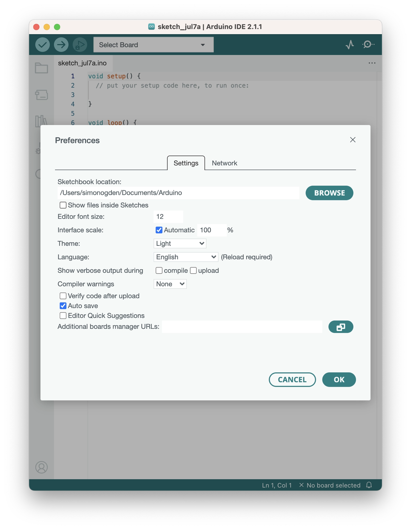
- Enter the following URL into the additional board manager URLs text box. If you need to use multiple board managers, you can click the small icon to the right of the text box and enter multiple URLs.
https://arduino.esp8266.com/stable/package_esp8266com_index.json
- Click OK.
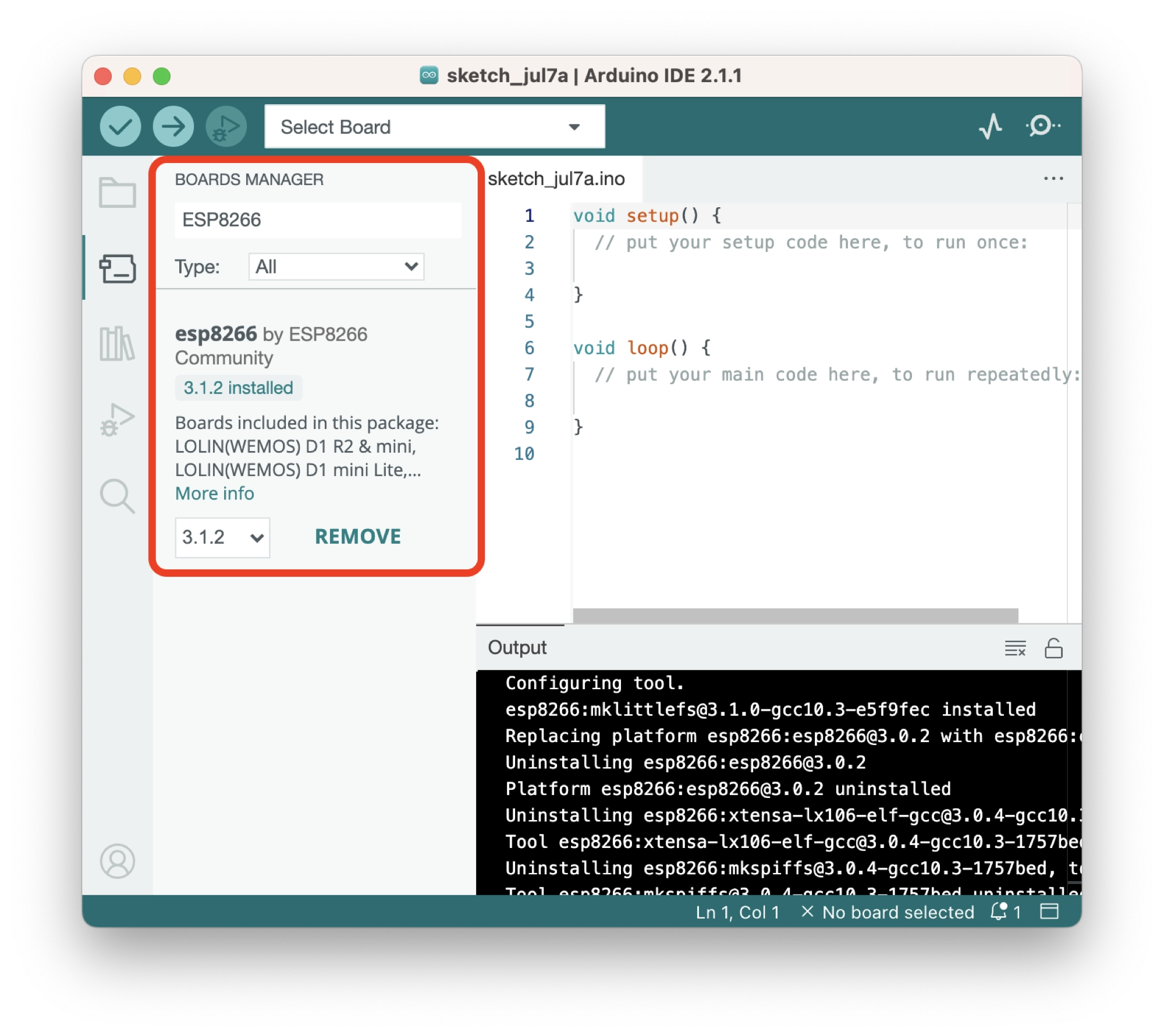
Adding ESP8266 Boards to Arduino
Now we can add the ESP8266 boards by clicking the tools > board > boards manager… option on the menu. Search for the ESP8266 library and install it.
How to Connect Arduino to an ESP8266 Board and Port
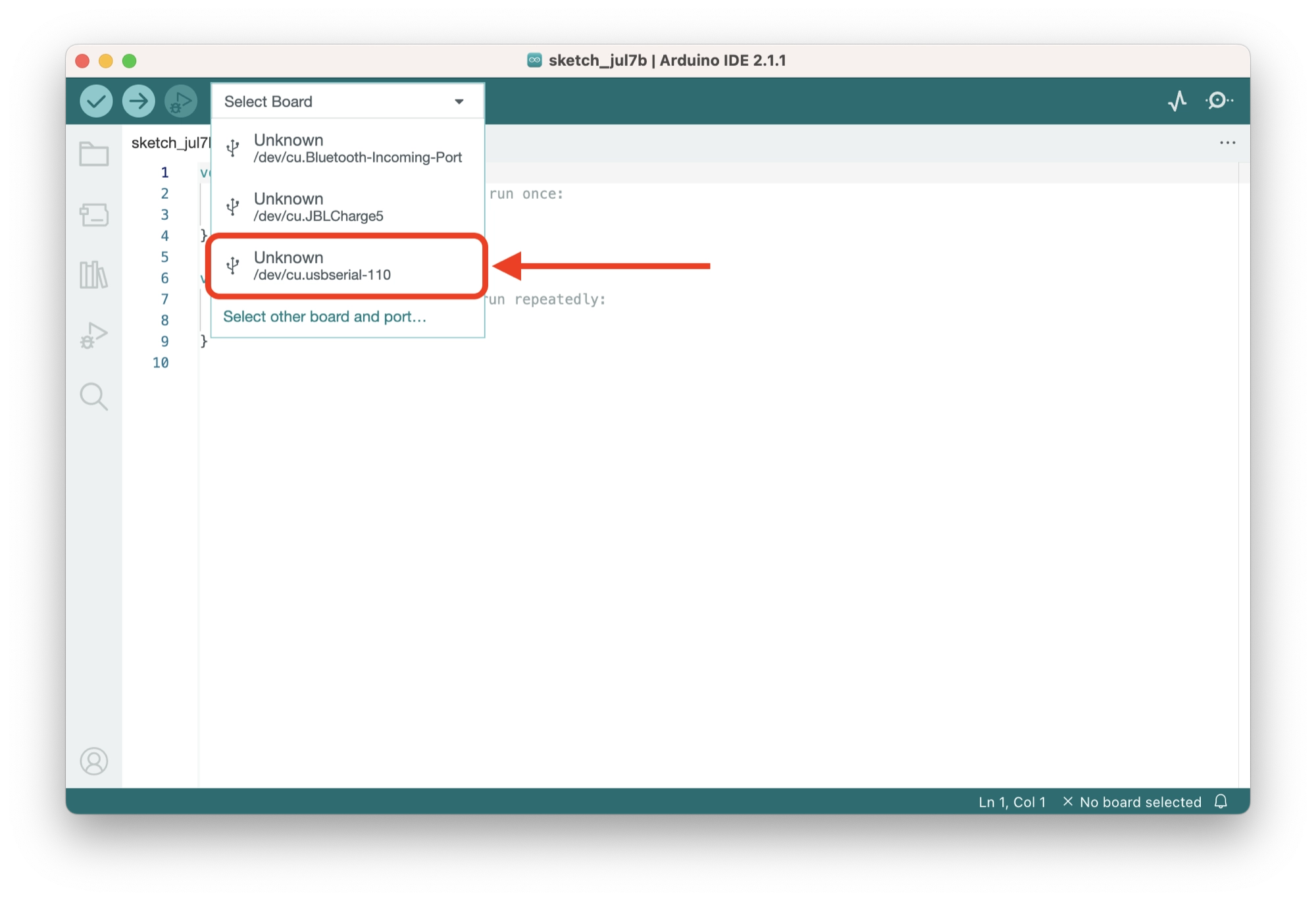
Once the ESP8266 boards library has been installed, we can connect to the ESP8266:
- Connect the ESP8266 to the computer using a USB cable.
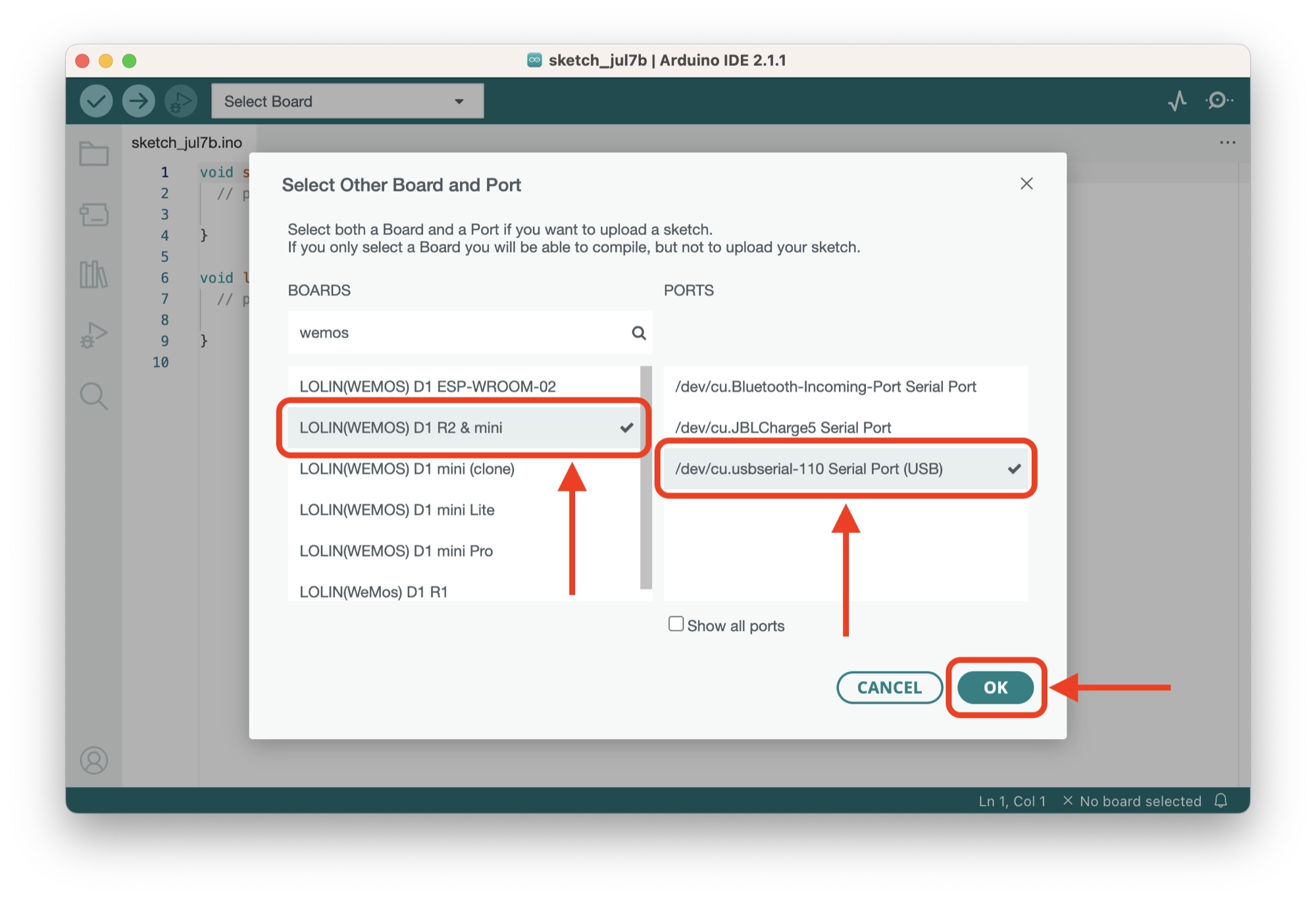
- Click the Select Board… drop down menu and select your board:
- Mac/Linux users: the port will be something similar to
/dev/tty.usbserial - Windows users: the port will be something similar to
COM6
- Mac/Linux users: the port will be something similar to
- Choose your ESP8266 in the left-hand column. In this example we are using the Wemos D1 Mini.
- Click OK.
Testing an ESP8266 Board with Blink
Let’s give the blink example a quick try just to make sure everything is configured correctly. Click file > examples > 01 basics > blink to load the sketch.
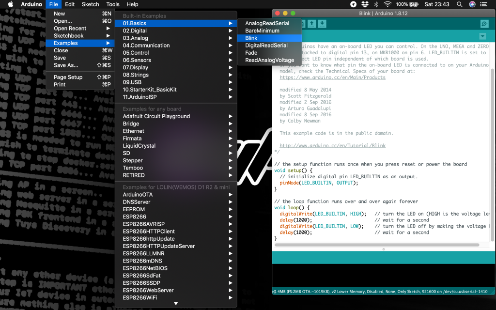
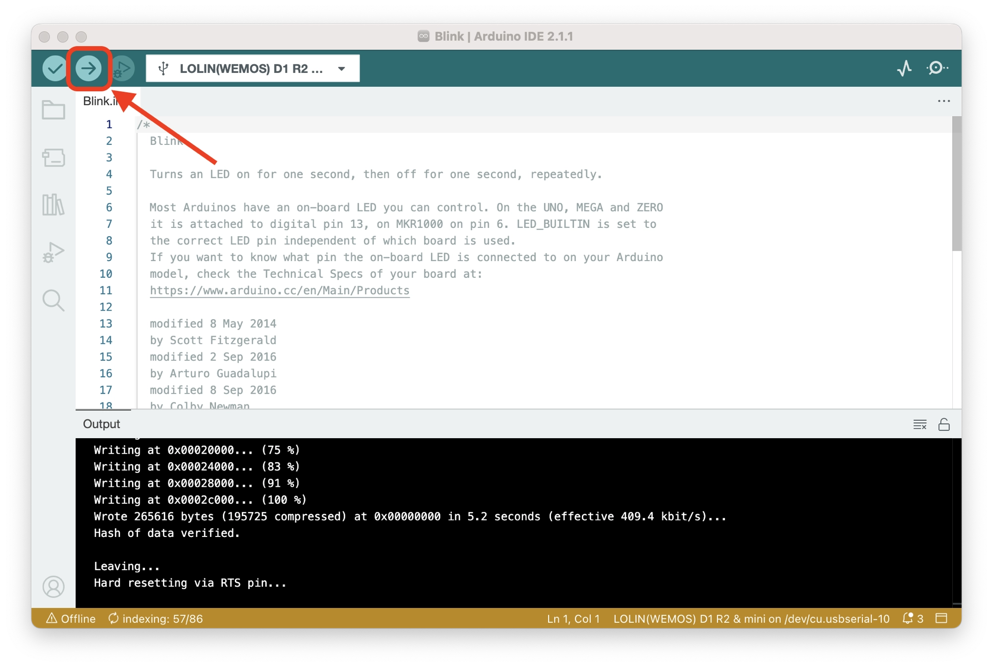
Once the sketch has opened, click the upload sketch button and wait a moment for the sketch to upload. If everything has been successful the LED on the Wemos D1 Mini should blink slowly.
Connecting the ESP8266 to WiFi
It is probably safe to assume that you will be wanting to connect your board to WiFi as a top priority. This is afterall one of the most powerful functions of the board!
So rather than stop at the blink sketch like most tutorials, let’s dive right in and connect the board to WiFi!
Including the ESP8266 WiFi Library
The first thing that we need to do is create a new sketch and then add the include for the ESP8266WiFi library. We will also define the SSID and password, be sure to change the values inside the quotes for your WiFi credentials.
#include <ESP8266WiFi.h>

// Set WiFi credentials
#define WIFI_SSID "YOUR WIFI NETWORK SSID"
#define WIFI_PASS "YOUR WIFI PASSWORD"

void setup() {
  // put your setup code here, to run once:

}

void loop() {
  // put your main code here, to run repeatedly:

}
Let’s break down the code line by line:
#include <ESP8266WiFi.h>
This line is called a preprocessor directive. It tells the compiler to include the ESP8266WiFi library, which provides functionality for connecting the ESP8266 microcontroller to a Wi-Fi network.
#define WIFI_SSID "YOUR WIFI NETWORK SSID"
#define WIFI_PASS "YOUR WIFI PASSWORD"
These two lines use the #define directive to create constants for the Wi-Fi network SSID and password. The WIFI_SSID constant represents the name (SSID) of your Wi-Fi network, and the WIFI_PASS constant represents the password required to connect to that network.
You should replace "YOUR WIFI NETWORK SSID" and "YOUR WIFI PASSWORD" with the actual SSID and password for your Wi-Fi network.
void setup() {
  // put your setup code here, to run once:
}
This is the setup function. It is a special function that is called once when the microcontroller starts up. In this case, the function is empty, indicated by the comment.
You can add your own code inside this function to perform any necessary setup tasks, such as initializing variables, configuring pins, or connecting to peripherals.
void loop() {
  // put your main code here, to run repeatedly:
}
This is the loop function. It is also a special function that is called repeatedly after the setup function. Any code you place inside this function will be executed over and over again in a loop.
This is where you typically put the main logic of your program, such as reading sensors, making decisions, and controlling outputs.
Setup the Serial Port
Next we will open the serial port so that we can receive a message in the serial window which tells us when the WiFi has been connected successfully.
void setup() {
  // Setup serial port
  Serial.begin(115200);
  Serial.println();
We will add this code inside of the setup function.
void setup() {This is the start of the setup function, which is called once when the microcontroller starts up.
  // Setup serial port
  Serial.begin(115200);
This line initializes the serial communication port. The Serial.begin(115200) function sets the baud rate for serial communication to 115200 bits per second.
Baud rate refers to the data transmission speed between the microcontroller and another device, such as a computer.
Serial communication is a way for the microcontroller to send and receive data to/from an external device (e.g., a computer) through a serial connection (usually using USB). It can be useful for debugging or printing messages to monitor the behavior of your program.
Serial.println();
This line prints an empty line to the serial port. It is used to add a line break or newline character to the output. This can be helpful for formatting the output or separating different pieces of information when printing messages.
By including this line, the microcontroller will print an empty line to the serial port immediately after it starts up.
Starting the ESP8266 WiFi Module
Following the serial port configuration, we can add the command to begin the WiFi. We will use the values for SSID and password declared earlier so make sure you set them correctly for your network.
  // Begin WiFi
  WiFi.begin(WIFI_SSID, WIFI_PASS);
This line initiates the process of connecting to a Wi-Fi network. The WiFi.begin() function is provided by the ESP8266WiFi library and takes two the parameters we defined earlier: WIFI_SSID and WIFI_PASS.
WIFI_SSID is a constant representing the name (SSID) of the Wi-Fi network you want to connect to. It should be replaced with the actual SSID of your network.
WIFI_PASS is a constant representing the password required to connect to the Wi-Fi network. It should be replaced with the actual password for your network.
By calling WiFi.begin(WIFI_SSID, WIFI_PASS), the microcontroller attempts to establish a connection to the specified Wi-Fi network using the provided SSID and password.
After calling this function, the microcontroller will go through a series of steps to connect to the network, including scanning for available networks, authenticating with the specified SSID and password, and obtaining an IP address.
Wait For a Connection
Next we will add some code that prints a message to the serial window to let us know that the ESP is trying to connect to the network.
We also need to add a while loop that iterates while the WiFi is not connected. This will prevent the program from continuing until a connection is established.
  // Connecting to WiFi...
  Serial.print("Connecting to ");
  Serial.print(WIFI_SSID);
  // Loop continuously while WiFi is not connected
  while (WiFi.status() != WL_CONNECTED)
  {
    delay(100);
    Serial.print(".");
  }
Let’s break it down:
  // Connecting to WiFi...
  Serial.print("Connecting to ");
  Serial.print(WIFI_SSID);
These lines print a message to the serial port to indicate that the microcontroller is attempting to connect to the Wi-Fi network. The message includes the text “Connecting to” followed by the value of WIFI_SSID, which represents the Wi-Fi network SSID.
The Serial.print() function is used to send data to the serial port for debugging or monitoring purposes. In this case, it prints the specified text to the serial port.
  // Loop continuously while WiFi is not connected
  while (WiFi.status() != WL_CONNECTED)
  {
    delay(100);
    Serial.print(".");
  }
This code creates a loop that continues executing until the microcontroller successfully connects to the Wi-Fi network (WL_CONNECTED is a constant indicating a successful connection). The loop is created using a while statement.
Within the loop, it waits for a short delay of 100 milliseconds (delay(100)) using the delay() function provided by the Arduino framework. This delay allows time for the Wi-Fi connection process to proceed.
After the delay, it prints a period (“.”) to the serial port using Serial.print().
This loop will continue until the microcontroller successfully connects to the Wi-Fi network. During this time, it will repeatedly delay for 100 milliseconds and print a period to the serial port.
Once the connection is established, the loop will exit, and the setup function will complete.
Printing the ESP8266 IP Address
Finally we can add an output to the serial window which prints the assigned IP address once a connection is established.
  // Connected to WiFi
  Serial.println();
  Serial.print("Connected! IP address: ");
  Serial.println(WiFi.localIP());

}
These lines print a message to the serial port indicating that the microcontroller has successfully connected to the Wi-Fi network. It also prints the IP address assigned to the microcontroller by the network.
The Serial.println() function is used to print an empty line to the serial port, which adds a line break or newline character to the output.
The Serial.print() function is used to send data to the serial port. In this case, it prints the text “Connected! IP address: ” followed by the value of WiFi.localIP(). The WiFi.localIP() function returns the local IP address assigned to the microcontroller by the Wi-Fi network.
By including these lines, the microcontroller will print a message indicating a successful connection and display the assigned IP address on the serial port.
Lastly, as this is the final code required for the setup, we can end the setup function with a closing curly brace (}).
Now that we have completed the code, we can review the completed project and proceed with testing the connection.
ESP8266 Simple WiFi Example Project
The completed code for the simple WiFi example project is as follows:
#include <ESP8266WiFi.h>
// Set WiFi credentials
#define WIFI_SSID "YOUR WIFI NETWORK SSID"
#define WIFI_PASS "YOUR WIFI PASSWORD"
void setup() {
// Setup serial port
Serial.begin(115200);
Serial.println();
// Begin WiFi
WiFi.begin(WIFI_SSID, WIFI_PASS);
// Connecting to WiFi...
Serial.print("Connecting to ");
Serial.print(WIFI_SSID);
// Loop continuously while WiFi is not connected
while (WiFi.status() != WL_CONNECTED)
{
delay(100);
Serial.print(".");
}
// Connected to WiFi
Serial.println();
Serial.print("Connected! IP address: ");
Serial.println(WiFi.localIP());
}
void loop() {
// put your main code here, to run repeatedly:
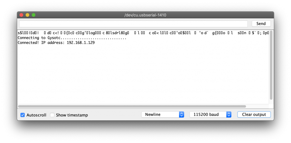
}Now that the code is complete we can go ahead and test our WiFi connection! First upload the sketch and then open the serial window once it has complete. Don’t forget to change the baud rate to 115200 to match the program.
Then press the reset button on the side of the D1 Mini and you should see an output like this. If the connection was successful, the IP address will be printed in the serial window.
How to Test the ESP8266 WiFi Connection
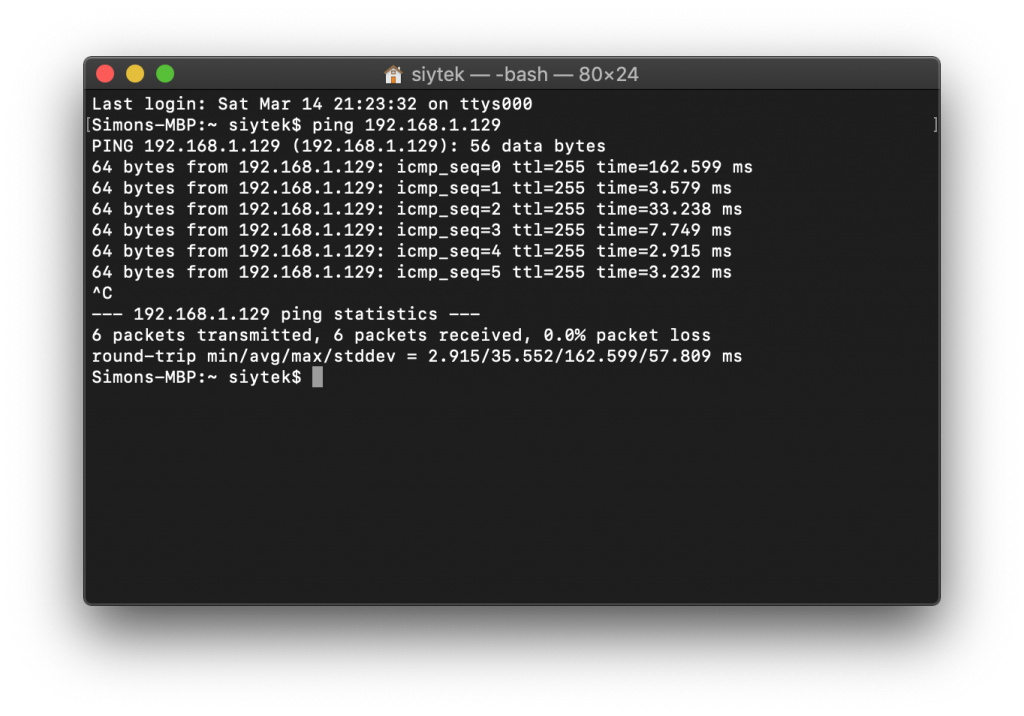
The ESP8266 WiFi can be tested using the ping command, which is accessible from the computer command line interface.
Ping is a network utility that sends a small packet of data from one device to another to test the reachability and round-trip time of the network connection.
In order to use ping to check the ESP8266 network connection, open a terminal window (macOS) / command prompt (Windows) and use the ping command followed by the IP address of the ESP8266:
ping <esp8266-IP-address>
The ping command sends data packets which are bounced back by the ESP8266. If the packets are returned with a given ping time (in milliseconds), this confirms that the network connection has been established.
Conclusion
The Wemos D1 Mini is an incredibly versatile and affordable tool that is highly valued by makers, smart home enthusiasts, and tech lovers alike.
While there are amazing solutions available that enable project development without coding, it is still beneficial to have the ability to build applications from scratch.
Arduino serves as an ideal platform for creating customized apps for the Wemos D1 Mini. With the setup process complete, you are now equipped and ready to unleash your creativity in developing your own applications!
Are you interested in uploading your sketch wirelessly over a Wi-Fi connection? Feel free to explore my tutorial on utilizing the Arduino IDE to perform Over-The-Air (OTA) flashing for devices.
Article Updates
July 6th 2023 : Codeblocks added and clarity of code improved. Additional descriptions added for each line/block of code to better explain how the code works. Featured image updated.
Article first published March 13th 2020.
Thanks so much for visiting my site! If this article helped you achieve your goal and you want to say thanks, you can now support my work by buying me a coffee. I promise I won't spend it on beer instead... 😏


bro love the way you write your article. It was very helpful and funny to read. Not only this one I have now read several articles of your website and they are amazing.