
So you need to flash Tasmota on to your device but your dog ate your FTDI adapter?
There are many different ways that we can flash Tasmota to our device, the reason being the very simple serial interface required to flash the ESP device.
If you have a Raspberry Pi lying around then you might want to check out this tutorial instead. However you can also use any Arduino board simply by utilising the onboard USB-to-serial interface.
If you don’t have an Arduino then it would definitely be worth getting one as they are super-versatile and useful, as shown in this tutorial!
Table of Contents
How to flash tasmota
I am current building a DIY Home Assistant thermostat and I need to flash a Sonoff Dual R2 for this project, therefore we will use it as a device example here.
However this tutorial will work with any Tasmota compatible device so long as you can make the wired connection.
If you are using a Tuya device, you can try flashing it over the air instead, to avoid having to open it up and attach wires.
It is also possible to flash Sonoff devices over the air using SonOTA but at the time of writing it is not compatible with the V2 firmware. Once this has been rectified I will add a tutorial on how to do this.
This tutorial will focus on the wired flashing method, whereby we connect our ESP device to an Arduino, then use the Arduino as a USB-to-serial bridge.
Requirements
- A Tasmota compatible device to flash
- An Arduino board
- A USB cable
- The Tasmotizer flashing software (or ESPTool for terminal/command line)
- A 3 way pin header
- Short length of wire
- Soldering iron and solder
Setup Arduino
The main chip on the Arduino board does not actually serve any purpose when flashing with ESPTool. With the wiring that we just completed, we will actually intercept the serial port on the secondary FTDI-to-USB chip that is usually used to flash the Arduino.
Before we connect our device to the Arduino board we need to load a sketch on to the Arduino that will ensure that it does not write anything on the serial port, as this would corrupt the flashing.
Go ahead and connect your Arduino to the USB port and then open the Arduino IDE and create a new sketch.
void setup() {
// put your setup code here, to run once:
}
void loop() {
// put your main code here, to run repeatedly:
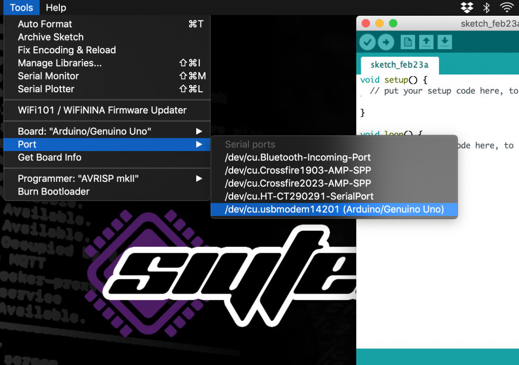
}Make sure your board and port are selected correctly and make a note of the port name.
In my case the port is labelled Arduino/Genuino Uno, however if you are unsure just disconnect your Arduino and see which device disappears.
Once you have the correct board and port selected, flash the blank sketch to the Arduino. After the writing has completed, disconnect your Arduino board from the USB port.
Wiring
The ESP8266 has the ability to be flashed over a serial connection, therefore we must locate the TXD and RXD pins on our device.
We also need to to make sure that both devices have their ground pins connected together.
Finally we may need to connect power depending on the device we are flashing. In the case of our Sonoff switch we will use power from the Arduino.
Soldering wires to the device
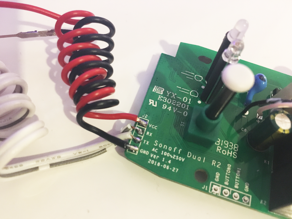
Many devices have points on the circuit board that were used in the factory to flash the firmware. Other devices such as the Sonoff switches even provide the connector with labels, very handy!
We will need to solder wires on to the TX and RX pins. We will also need to solder a wire on to the GND pin as the devices should always have their grounds tied together regardless of whether or not the device is powered from the programmer.
Depending on whether we will power the device with the Arduino or by its own power supply will depend on whether we also need a wire soldered to Vcc.
For the Sonoff switches we need to connect the power, so we will solder the fourth wire to Vcc. Some devices such as the MagicHome LED controllers should be powered from their own power supplies and the Vcc wire should not be connected.
The ESP8266 is MUST be powered from 3.3V, if we connect Vcc to 5V we will damage the chip. However the IO pins are 5V tolerant, therefore we can use a programmer that communicates with a 5V signal.
Attach the connector
We will need to cut four lengths of wire, then strip and tin both ends. On one end of each wire you will need a suitable connector that can be plugged into the Arduino.
If you are not fortunate enough to have these terminals and a crimper lying around, you can insert some male pin header into the Arduino and solder to this instead.
Connect to the Arduino
So now we should have four wires connected to our device, TX, RX, Vcc and GND. We can go ahead and connect it to the Arduino.
One thing to note about the Sonoff Dual R2 is that the TX and RX pins are reversed. It took me a while to figure this out!
Usually you would connect the TX pin to RX on the programmer and the RX pin to TX on the programmer. However the Sonoff needed TX connected to TX and RX connected to RX.
Connect TX and RX
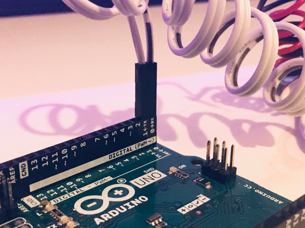
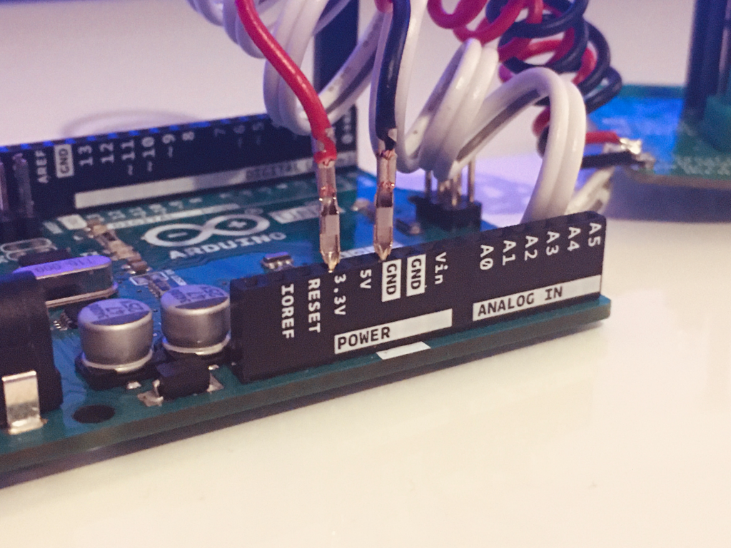
First let’s connect the TX and RX wires from our device to the TX and RX pins of our Arduino respectively.
These pins are also labelled as ‘0’ and ‘1’ as they share their function with digital pins 0 and 1.
Connect the power
Next we can go ahead and connect our power and ground wires. Make absolutely sure that you connect Vcc to 3.3V! I would recommend checking this a couple of times before you plug in the USB cable!
Connect GPIO0 to GND
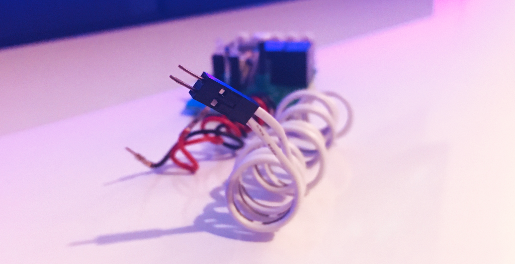
In order to put the ESP device into flashing mode we need to connect the GPIO0 to GND before we power up the device. This is sometimes labelled as IO0 or Button0.
On the Sonoff circuit there is a second header with Button0 and GND so we can place a temporary jumper wire between them without needing to solder it. You could also just short them together with a pair of tweezers.
Connect the USB cable
Now that you have connected your device to the Arduino, check one more time that you have connected Vcc to 3.3V! Then if you are sure everything is correct, go ahead and plug your Arduino into the USB port.
If the device has successfully entered flashing mode it is usually evident as the LED will remain off when powered up.
Flashing Tasmota
There are a couple of ways you can flash your device using ESPTool but the easiest way is to use the Tasmotizer. I have a detailed post on how to install and use the Tasmotizer, but we will cover it again here very breifly.
Firstly we need to open Tasmotizer and select our Arduino board in the select port dropdown menu. Use the same port that you made a note of when configuring the Arduino.
Under the select image option, choose release unless you plan to flash either the development version of Tasmota or your own .bin file.
Make sure that the checkbox next to erase flash is ticked. I would recommend erasing the ESP device prior to flashing to prevent any problems.
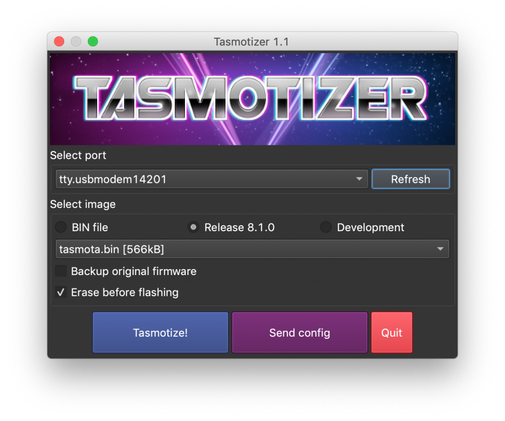
Once done you are ready to flash, so go ahead and hit the Tasmotize button! Flashing will take a minute or two so maybe go grab yourself a nice cold beverage.
Once flashing has complete, Tasmotizer will ask you to power cycle the device. First remove the jumper between GPIO0 and GND, then disconnect and reconnect the USB cable.
If everything was successful you will see your new Tasmota device appear as a WiFi access point.

Whats Next?
Now you can go ahead and configure Tasmota using this detailed tutorial. It covers the complete configuration, including how to set up MQTT for auto discovery in Home Assistant.
I hope that you found this tutorial useful, don’t forget to visit some of my other cool Home Assistant tutorials!
Thanks so much for visiting my site! If this article helped you achieve your goal and you want to say thanks, you can now support my work by buying me a coffee. I promise I won't spend it on beer instead... 😏