
ESP8266 WiFi devices can be conveniently flashed over the air (OTA) using the Arduino IDE. All that is required is a little additional code in the sketch in order to make the WiFi serial port appear in the Arduino IDE.
This is very handy if you wish to install a device such as the Wemos D1 Mini in a remote location and still need to make firmware updates.
It can also save having to keep connecting a device to the USB if it sources power by another method.
This tutorial we will cover the necessary additions required to make a sketch compatible with OTA flashing.
Table of Contents
Prerequisite
You will need to have the Arduino IDE installed and running. I would recommend heading over to the website and getting the latest version. You will also need an ESP8266 board, I would recommend the Wemos D1 Mini used in this series of tutorials.
This tutorial will follow on from the previous tutorial detailing how to add the Wemos D1 Mini to the Arduino IDE. Although this was written for the D1 Mini, I would recommend you first try the code from this tutorial on your ESP8266 device.
Writing the code
We will assume that you already have a project running on your ESP8266 board that has been connected to you WiFi network. For this tutorial we shall use the example code from the previous tutorial, I would recommend checking it out if you have not yet connected your device to WiFi.
Connecting to WiFi
If you don’t yet have a project connected to WiFi, copy the sample code below into a new project and save it. Upload the sketch to your board and check that the IP address is reported back in the serial monitor window.
#include <ESP8266WiFi.h>

// Set WiFi credentials
#define WIFI_SSID "YOUR WIFI NETWORK SSID"
#define WIFI_PASS "YOUR WIFI PASSWORD"

void setup() {
  // Setup serial port
  Serial.begin(115200);
  Serial.println();

  //Begin WiFi
  WiFi.begin(WIFI_SSID, WIFI_PASS);

  // Connecting to WiFi...
  Serial.print("Connecting to ");
  Serial.print(WIFI_SSID);
  // Loop continuously while WiFi is not connected
  while (WiFi.status() != WL_CONNECTED)
  {
    delay(100);
    Serial.print(".");
  }

  // Connected to WiFi
  Serial.println();
  Serial.print("Connected! IP address: ");
  Serial.println(WiFi.localIP());

}

void loop() {
  // put your main code here, to run repeatedly:

}
Add basicOTA.h
Next we need to add the basicOTA.h file to the project. Simply download and clone the repository and extract it from the .zip file. Alternatively you can create a new file and paste it from the raw file available here.
Add the includes
Once you have the file, move it to the same directory as your project. We can then add an include for this file. Speech marks indicate to the IDE that the file is located in the project directory and not the library folder. We also need to include the ArduinoOTA.h library.
See line 2 to 3:
#include <ESP8266WiFi.h>
#include <ArduinoOTA.h>
#include "basicOTA.h"

// Set WiFi credentials
#define WIFI_SSID "YOUR WIFI NETWORK SSID"
#define WIFI_PASS "YOUR WIFI PASSWORD"

void setup() {
  // Setup serial port
  Serial.begin(115200);
  Serial.println();

  //Begin WiFi
  WiFi.begin(WIFI_SSID, WIFI_PASS);

  // Connecting to WiFi...
  Serial.print("Connecting to ");
  Serial.print(WIFI_SSID);
  // Loop continuously while WiFi is not connected
  while (WiFi.status() != WL_CONNECTED)
  {
    delay(100);
    Serial.print(".");
  }

  // Connected to WiFi
  Serial.println();
  Serial.print("Connected! IP address: ");
  Serial.println(WiFi.localIP());

}

void loop() {
  // put your main code here, to run repeatedly:

}
Call the setup OTA function
Next we need to call the setup_OTA function from the setup function in our project. This will execute all of necessary steps from basicOTA.h needed to setup OTA flashing in our project.
See line 32 to 33:
#include <ESP8266WiFi.h>
#include <ArduinoOTA.h>
#include "basicOTA.h"

// Set WiFi credentials
#define WIFI_SSID "YOUR WIFI NETWORK SSID"
#define WIFI_PASS "YOUR WIFI PASSWORD"

void setup() {
  // Setup serial port
  Serial.begin(115200);
  Serial.println();

  //Begin WiFi
  WiFi.begin(WIFI_SSID, WIFI_PASS);

  // Connecting to WiFi...
  Serial.print("Connecting to ");
  Serial.print(WIFI_SSID);
  // Loop continuously while WiFi is not connected
  while (WiFi.status() != WL_CONNECTED)
  {
    delay(100);
    Serial.print(".");
  }

  // Connected to WiFi
  Serial.println();
  Serial.print("Connected! IP address: ");
  Serial.println(WiFi.localIP());

  // Setup Firmware update over the air (OTA)
  setup_OTA();

}

void loop() {
  // put your main code here, to run repeatedly:

}
Poll ArduinoOTA.handle
We also need to poll ArduinoOTA.handle in our main program loop to check for OTA firmware updates. This should be added somewhere in the loop function.
See line 39 to 40:
#include <ESP8266WiFi.h>
#include <ArduinoOTA.h>
#include "basicOTA.h"

// Set WiFi credentials
#define WIFI_SSID "YOUR WIFI NETWORK SSID"
#define WIFI_PASS "YOUR WIFI PASSWORD"

void setup() {
  // Setup serial port
  Serial.begin(115200);
  Serial.println();

  //Begin WiFi
  WiFi.begin(WIFI_SSID, WIFI_PASS);

  // Connecting to WiFi...
  Serial.print("Connecting to ");
  Serial.print(WIFI_SSID);
  // Loop continuously while WiFi is not connected
  while (WiFi.status() != WL_CONNECTED)
  {
    delay(100);
    Serial.print(".");
  }

  // Connected to WiFi
  Serial.println();
  Serial.print("Connected! IP address: ");
  Serial.println(WiFi.localIP());

  // Setup Firmware update over the air (OTA)
  setup_OTA();

}

void loop() {

  // Check for OTA updates
  ArduinoOTA.handle();

}
Flash the LED to debug
As we will be connecting the Arduino IDE to WiFi and not the standard serial port, we will not be able to receive information in the serial console.
In order to confirm that we have updated the firmware from the previous tutorial, we will add some code to blink the LED.
See line 11 to 12 and 46 to 50:
#include <ESP8266WiFi.h>
#include <ArduinoOTA.h>
#include "basicOTA.h"

// Set WiFi credentials
#define WIFI_SSID "YOUR WIFI NETWORK SSID"
#define WIFI_PASS "YOUR WIFI PASSWORD"

void setup() {

  // Setup LED
  pinMode(LED_BUILTIN, OUTPUT);

  // Setup serial port
  Serial.begin(115200);
  Serial.println();

  //Begin WiFi
  WiFi.begin(WIFI_SSID, WIFI_PASS);

  // Connecting to WiFi...
  Serial.print("Connecting to ");
  Serial.print(WIFI_SSID);
  // Loop continuously while WiFi is not connected
  while (WiFi.status() != WL_CONNECTED)
  {
    delay(100);
    Serial.print(".");
  }

  // Connected to WiFi
  Serial.println();
  Serial.print("Connected! IP address: ");
  Serial.println(WiFi.localIP());

  // Setup Firmware update over the air (OTA)
  setup_OTA();

}

void loop() {

  // Check for OTA updates
  ArduinoOTA.handle();

  // Blink LED
  digitalWrite(LED_BUILTIN, HIGH);
  delay(100);
  digitalWrite(LED_BUILTIN, LOW);
  delay(100);

}
Alternatively you could use a seperate serial terminal to read the data from the serial port if you have your device connected to USB for debugging.
However blinking the LED provides visual feedback regardless of whether the device is connected to the USB port.
Flashing
That’s it! Our application is now ready to be flashed over the air. However we first need to flash the new code to our device over the serial connection in order to enable OTA flashing.
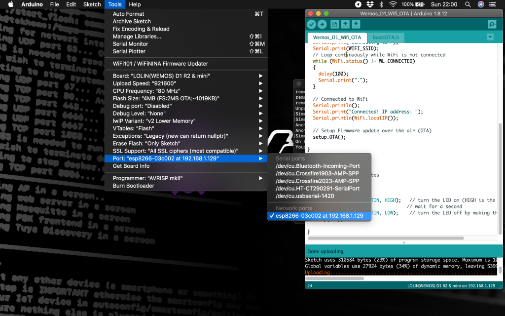
Go ahead and flash the code onto the device over the serial connection. Once the new sketch has been uploaded you will be able to select the WiFi serial port from tools > Port > your_device_ip_address.
Conclusion
Adding the ability to flash your application over the air is both convenient and necessary in certain circumstances. The Arduino ESP Core has built-in OTA functionality that is easy to leverage with some simple code.
Why not check out some more awesome ESP device articles here on my website to get some ideas for your next project!
Thanks so much for visiting my site! If this article helped you achieve your goal and you want to say thanks, you can now support my work by buying me a coffee. I promise I won't spend it on beer instead... 😏