
Most websites will just tell you to put a smart bulb in an existing fixture… but what if there is another way? What if your favorite lamp doesn’t take a traditional bulb?
In this post I show the process of converting a lamp to a smart lamp without using a smart bulb. This method is a lot more in depth but it can be applied to a much wider range of lights.
I have been noticing a certain trend for the use of LED strip lights within home lighting fixtures. Then my birthday came and I was given a beautiful floor standing lamp as a gift, which contained white LED strip for the source of light.
It’s a beautiful lamp but there is one problem… its dumb.
In this first part of a two part series we will look at the electronic specification of the lamp and cover some very light electronic circuit theory in order to understand how we can modify the lamp to make it a smart lamp!
At present my lamp cannot be connected to Home Assistant, or any smart home hub or app for that matter. It is such a beautiful lamp and would look very atmospheric, if only I could dim it!
Further to this it is very bright so it ruins most of my atmospheric living room scenes and I rarely have the lights on full brightness in the living room. There is no other option, I must make this lamp smart!
Table of Contents
Assessing the modification
Now if this was a lamp with a standard bulb we would not need a tutorial, we would simply add a smart bulb. Alternatively we could use a standard bulb and wire a dimmer in between the plug and the lamp.
However this lamp consists of a series of LED strips, so what can we do? Thankfully the solution is quite simple, but first we must inspect the lamp more closely.

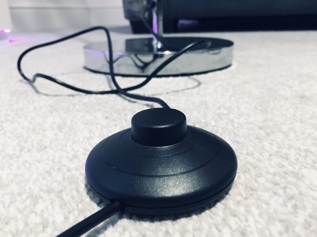
The switch
I am absolutely certain that there is nothing smart about this switch, it is simply an on/off switch that makes and breaks the circuit, therefore we can leave put it in the on position and forget about it, no need to remove it.
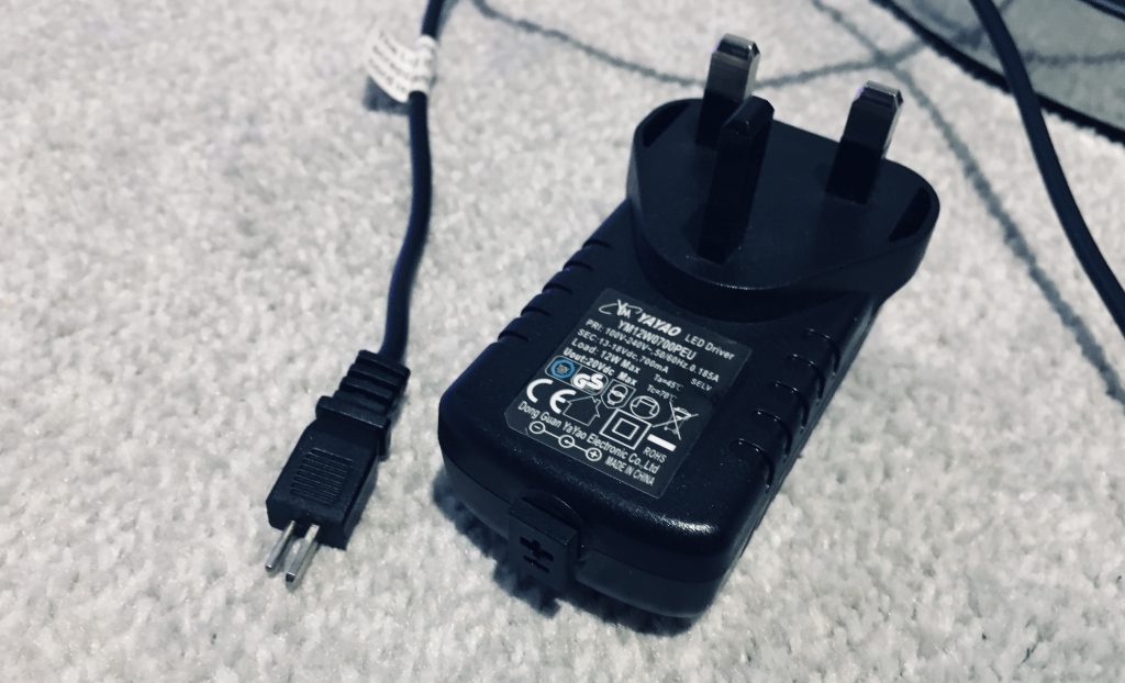
The power supply
The power adapter conveniently has a 2-pin DIN plug separating it from the switch. This is very unusual as I would expect this wire to be molded into the plug. If the wire was molded then we could simply cut it at some point between the plug and the switch.
Alternatively we could open up the switch and disconnect the wires there. As long as we put some kind of break between the power supply and the LED strip, we can add our smart home controller into the gap.
What we are hoping for is that the LED strip runs from 12 volts DC. Firstly, this is a safe voltage to work with, we won’t be opening up the power supply so no risk of a shock from the mains. Secondly this is a very common voltage output by WiFi LED controllers that operate single colour LED strips. This means that we can select from a large range of controllers to use with our lamp.
Disclaimer: Caution must still be taken, your lamp may be powered from mains voltage and therefore you must NOT attempt to modify your lamp unless you are absolutely confident you understand what you are doing. You may also cause damage to your lamp, so proceed at your own risk.
In my case the power supply simply delivers current to the LED strip and the lamp is switched on and off by a mechanical switch. If you are working with a ceiling or wall mount fixture you probably won’t have a switch. In which case you need to splice the controller between the transformer and LED strip.
In the case of a ceiling light or any light with an exposed transformer, take extreme caution operating the device with the transformer exposed as you a liable to receive a shock at FULL MAINS VOLTAGE if you touch the wrong place. Make ABSOLUTELY SURE you understand what you are doing before you attempt to modify these kind of light fixtures.
So let’s examine the stock power supply, first we will check the secondary winding output on the power supply. Alternatively you can just measure it with a multimeter.
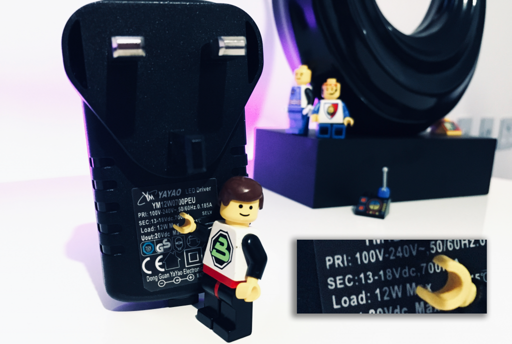
The secondary winding is given here.
SEC: 13-18Vcd 700mA
This is a little unusual as we would hope that this would be a fixed 12 volt supply. In my case the LED strip in the lamp is marked 12 volts, although this may not be the case for a different LED strip. Therefore we can take a look at some basic electronic theory to see if we can understand what is happening here and whether a standard 12 volt controller will be suitable.
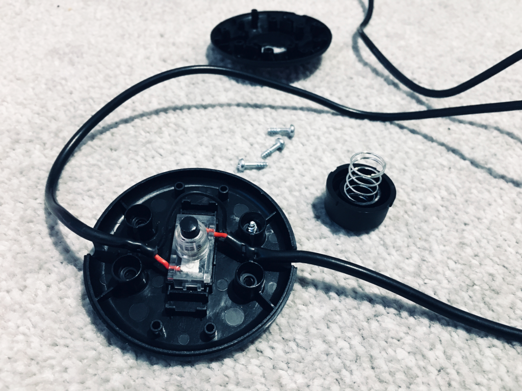
The first thing I did was open up the switch and check to see if there was a regulator inside. This is a small device commonly found in power supply circuits that would provide a fixed 12 volt output, and usually requires a voltage of at least 1 volt higher than its fixed output. It would be the most obvious reason, however upon disassembling I found there to be no regulator inside.
LED Strip science
Let’s dive in to some basic electronics theory. You don’t have to be an expert electronic engineer to make some basic modifications but I would certainly recommend trying to get a grasp of the basics.
Forward Voltage
In simple terms we can say that when a voltage is applied across an LED, some of that voltage is ‘lost.’ This is known as the forward voltage of the LED and it is denoted as Vf. The forward voltage for an LED differs with the colour, but white LEDs are commonly around 3 volts.
When LEDs are wired together end to end, we say that they are wired in series. The forward voltages of all LEDs wired in series are summed together, for example if we wire three white LEDs in series, the total voltage drop will be as follows.
3 + 3 + 3 = 9 volts
It is good practice to ensure that the voltage used to power a chain of LEDs is around 1 volt higher than the total forward voltage. In our example this would mean that the minimum voltage required to power the three LEDs in series would be 10 volts.
So what happens to the rest of the voltage? An LED also requires an additional component wired in series in order to limit the current flowing through it. The internal resistance within the LED alone is not enough to adequately limit the current flow.
Current limiting resistor
We need to use a resistor to regulate the current so we don’t burn everything out. Think of it like a gas barbeque, we need to use a regulator on the gas bottle otherwise the pressure from the gas would blow the burner sky-high!
The resistor prevents too much current flowing through our LEDs and this is also where our remaining voltage ends up. If we use a 12 volt power supply with our example of three LEDs in series, we will drop 3 volts across each LED. Therefore we will drop a total of 9 volts across all three LEDs wired in series and the remaining 3 volts will end up across the current limiting resistor. Here is a basic diagram of this arrangement made with this awesome free online circuit simulator.
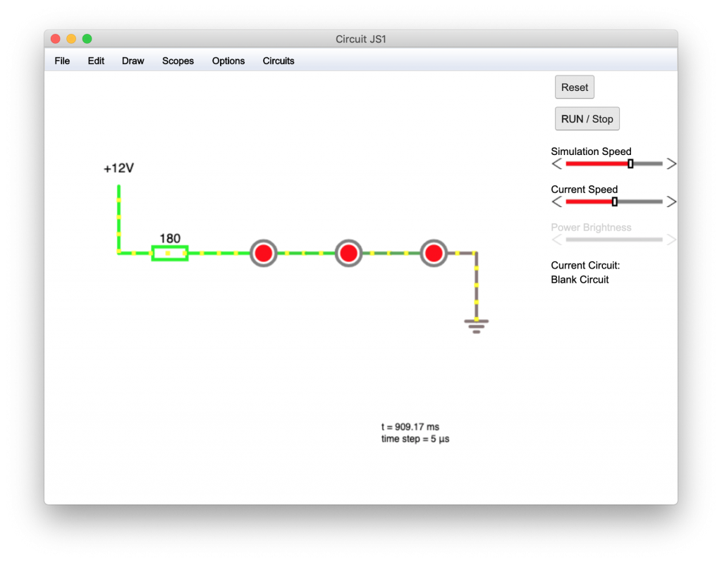
Stick with me! It will all become clear in one moment and this explanation should make some sense. Now we know that the voltage across the resistor is 3 volts, but what about current?
LED current
The current required to run the LED (as well as the forward voltage Vf) is specified in the datasheet, a sort-of-manual for the LED made available by the manufacturer for electronics engineers to use as a reference when designing circuits.
It would be fairly common to run an LED like this from a current of around 60 milliamps (mA), which is the same as 0.06 amps (A). This is the amount of current we need to have flowing through our LEDs, therefore the resistance must be calculated in order to achieve it.
We know that the voltage across the resistor will be 3 volts and we want 60mA of current to flow to illuminate the LEDs. We can use the ohm’s law equation to calculate the value of resistance required.
voltage (V) = Current (I) x Resistance (R)
V = I x R
We can rearrange this equation in terms of the resistance.
R = V / I
Then we can substitute in our values for voltage across the resistor and current.
R = 3 / 0.06
R = 50 ohms
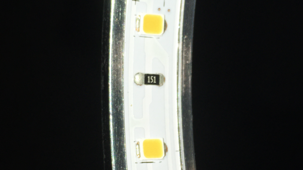
Now that we have calculated a value, we can further examine the LED strip in order to see the actual value of the resistor used. Here we find that it is in fact 150 ohms. You can use a tool like this one to look up the numbers on top of the resistor.
So what’s going on here? We can rearrange our equation to find the voltage required across the resistor, which will deliver a current of 60mA and illuminate the LEDs to full brightness.
V = I x R
V = 0.06 x 150
V = 9 volts
Very interesting! We need 9 volts across the resistor to deliver 60mA. Therefore to calculate the required supply voltage we must have 9 volts across the resistor and a further 9 volts that we will drop across the LEDs. We will add these two voltages together to get the total voltage required.
This means we need an 18 volt power supply to illuminate our LED strip to its full brightness. This is the upper limit of the range given for our power supply.
So what happens if we only deliver the minimum 13 volts? We drop 9 volts across the LEDs as before, but we are only left with 4 volts across our resistor. Using this value for voltage and 150 ohms from the resistor that we found on the LED strip, we can calculate the current supplied to the LEDs.
I = V / R
I = 4 / 150
I = 0.27 amps
As you can see we only get 27mA of current through our LEDs, a little less than half of the current that we would get if our power supply was giving us 13 volts. Wowzers!
LED brightness
So one might understandably assume that this particular lamp could vary in brightness by over half depending on the voltage output by the power supply. However this is not entirely the reality, and I will explain why.
Although the relationship between the current supplied to the LED and the amount of luminance it gives is proportional, the way that the human eye perceives brightness is not linear. This means that if we supply an LED with half of its maximum current, it will not look half as bright. It will actually look a brighter to us despite the fact that if we measured the light output, it would be half as much.
Confusing right?! I think it is easier to explain it with a graph. The following graph shows how the human eye perceives brightness.
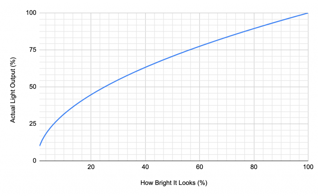
This graph shows the actual light output from the LED as a percentage vs the brightness that will actually be perceived as a percentage. As you can see, the human eye is more sensitive to changes in brightness at lower levels of luminance.
Our calculations suggest that running the LED strip from the lowest end of the voltage range given by our power supply will produce approximately half of the brightness. However if we look at the graph, the perceived brightness to our eyes is actually close to 75%. This means even though we are running the LED at half the current, it will only look one quarter dimmer to our eyes!
What about a 12 volt controller?
We can perform our calculation again but this time considering the 12 volts supplied from a common WiFi controller. Subtracting the 9 volt drop across the three LEDs means that we will have 3 volts across the resistor.
I = V / R
I = 4 / 150
I = 0.20 amps
This means that we will be supply the LEDs with one third of the current required to achieve maximum brightness. Looking at our graph above, we can expect the perceived brightness to be around 60%.
So what does all of this tell us?
Well, we already knew that it was acceptable to run this lamp from between 13 and 18 volts as it was given on the power supply. We know that the lower end of this range will give us a perceived brightness of around 75%. We also know it is perfectly acceptable to use a standard 12 volt WiFi controller, but can probably expect around 60% brightness.
Regarding the LED strip itself, we know by calculation that there must be three LEDs wired in series. Having less than three LEDs would result in a higher voltage across our resistor because the forward voltage drop would be less, which could cause problems if we try to run the LED strip from the maximum 18 volts. Having more than three LEDs in series would result in a forward voltage greater than our transformer minimum voltage of 13 volts, which could also cause problems.
Also you may be wondering why I am referencing only three LEDs in series, when the LED strip has many more LEDs! Remember our diagram from earlier showing the three LEDs in series with the resistor?
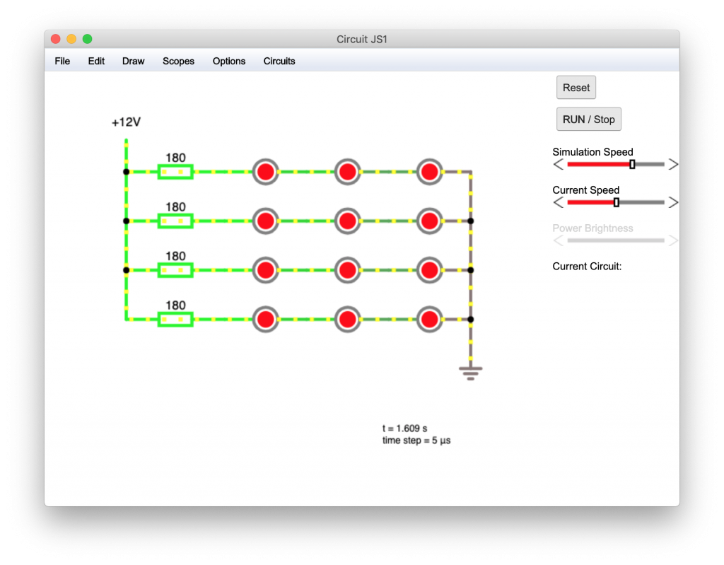
Quite simply we can wire many of these series circuits together in parallel to allow for many more LEDs. When wired in parallel the voltage is the same across each group of LEDs but the current is split.
If we consider our example running at the highest end of the voltage range, each group of parallel LEDs will add another 60 mA of current draw to the power supply.
So if we wanted twelve LEDs for example, we could have four groups of three LEDs. Each of the four groups would draw 60mA, giving us a total load on the power supply of 240mA. Note that each group of LEDs requires its own resistor.
Next, the fun part…
So now that we have a good understanding of the electronics inside our LED lamp we can get on to the fun part, adding the controller and making the lamp smart!
In part 2 of this article we will take a look at a suitable controller and go through the necessary steps in order to make our lamp smart!
Thanks for tuning in and I hope that you learnt something useful here, please let me know what you thought in the comments.
Thanks so much for visiting my site! If this article helped you achieve your goal and you want to say thanks, you can now support my work by buying me a coffee. I promise I won't spend it on beer instead... 😏


