
When learning Arduino or any other maker type platform it can really help to work to an example that produces striking results.
Personally I find LED matrix projects incredibly rewarding to build as the visual output can be very satisfying!
It is possible to produce some really cool projects with relatively simplistic code and hardware when using LEDs. The Wemos LED Matrix shield for the D1 Mini form factor is the ideal starting point.
- Prerequisite
- How Does The Wemos Matrix LED Shield Work?
- How To Install The Wemos Matrix LED Library
- How To Use The Wemos Matrix LED Library
- What Else Can The Wemos Matrix LED Do?
- Conclusion
Prerequisite
In order to follow this tutorial you will need a few things to get started. If you are completely new to the Wemos D1 Mini then I would recommend first checking out this guide.
You will need the following:
- A Wemos D1 Mini board
- A Wemos LED Matrix shield
- Soldering iron and some solder (to attach the pin header, if necessary)
- A USB-A to Micro-B cable
First you should install the Arduino IDE and set up the Wemos D1 Mini board, in order to be able to program the D1 Mini. You may also need to solder the headers on to both the Wemos D1 Mini and Matrix shield.
If you are new to soldering headers onto these boards then don’t worry! It really is quite simple. The following video gives a good explanation showing how to do this, so take a minute to check it out:
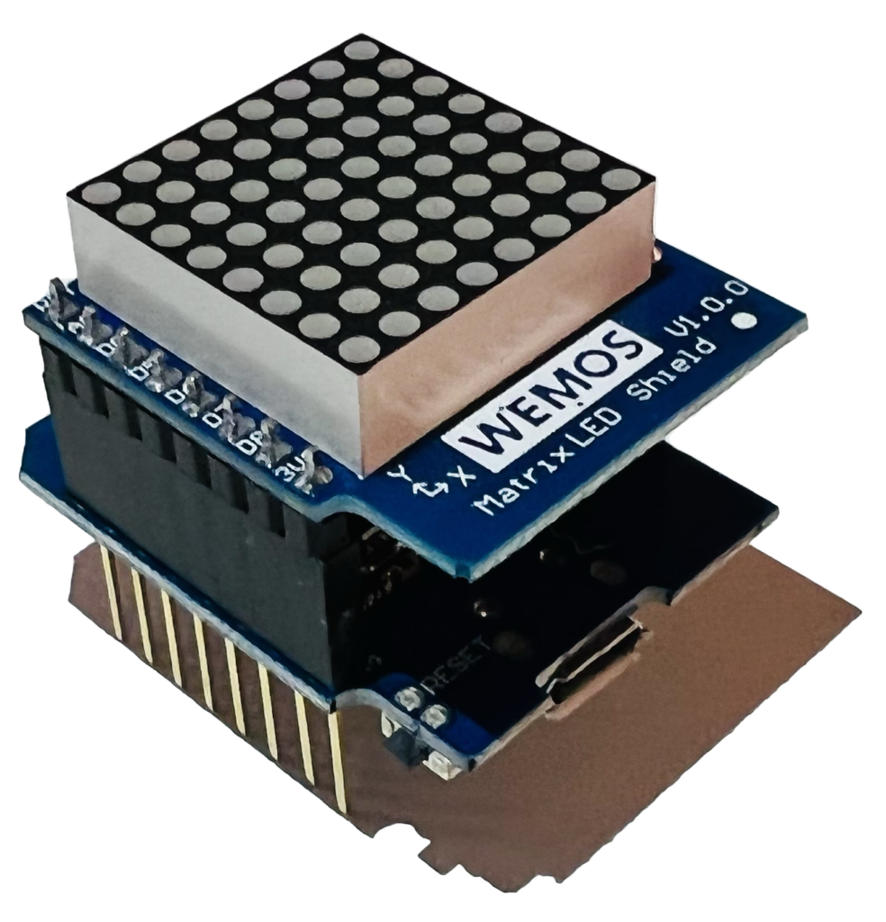
Once you have soldered on the headers, plug the matrix shield into the main D1 Mini board and you are good to go!
It should look something like this.
How Does The Wemos Matrix LED Shield Work?
The Wemos Matrix LED Shield uses the TM1640 matrix driver IC. Further information about the chip is available here in the datasheet.
Luckily all of the hard work has been done for us and the shield has all necessary components for functioning. However it can help to understand how it works, so let’s take a look at the schematic.
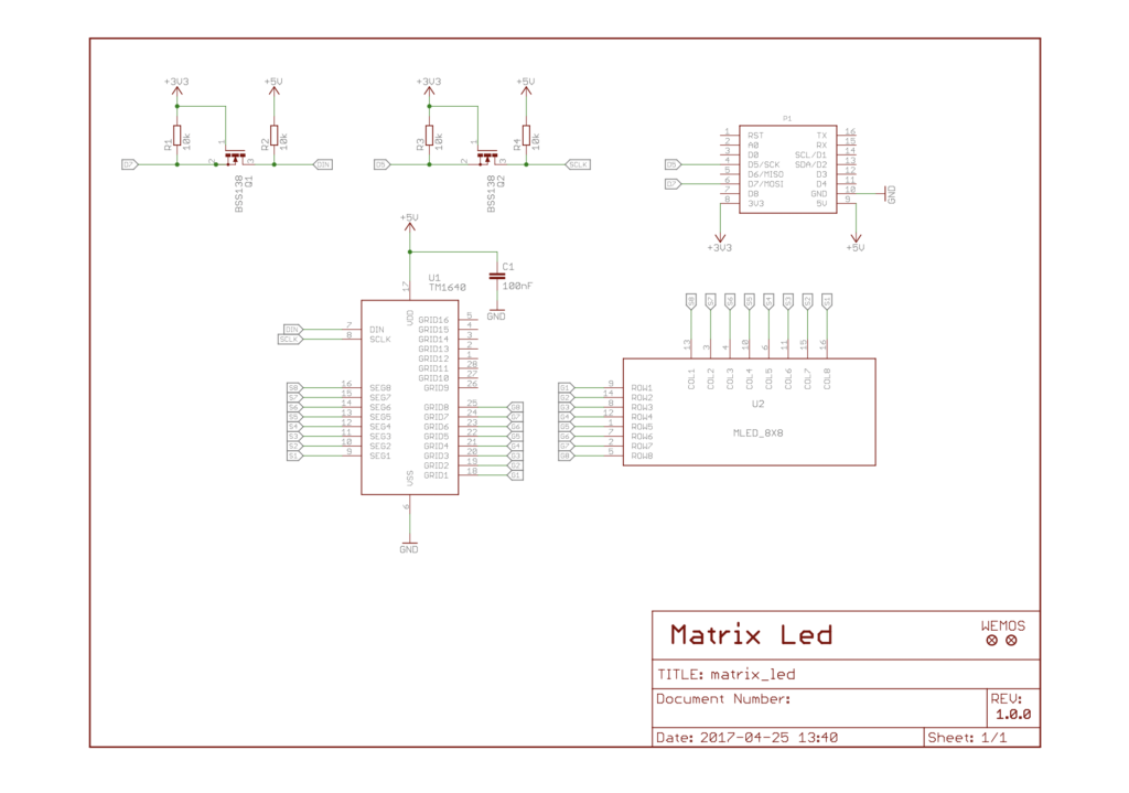
The schematic is actually quite simple. P1 represents the Wemos D1 Mini (in the shield design this is the headers that the Wemos D1 Mini plugs in to).
The LED matrix represented by U2 in the schematic is a single component on top of the shield, however it has no internal circuitry and is just a matrix of LEDs connected together as shown in the following diagram.
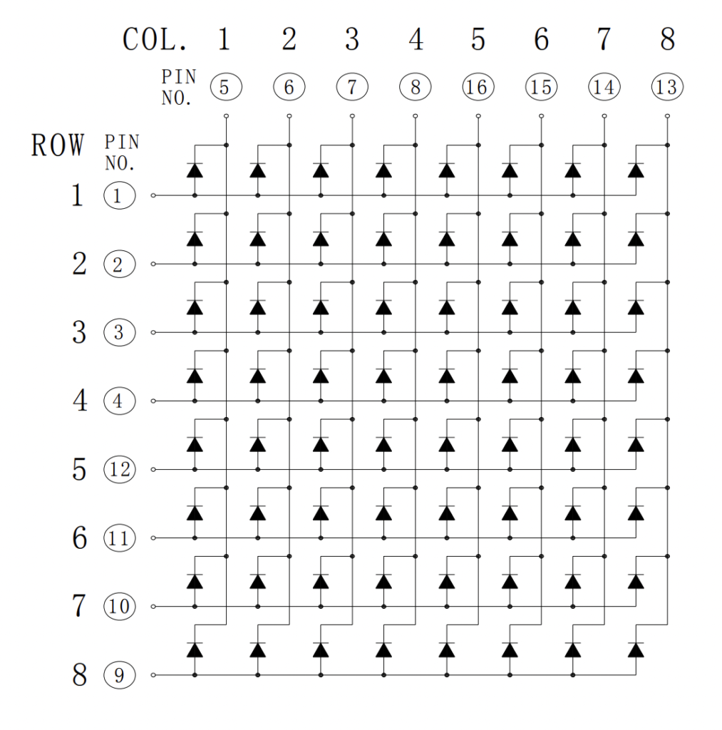
The TM1640 driver chip represented as U1 in the schematic connects to the rows and columns of the LED matrix. The driver chip can illuminate any combination of 8 LEDs in each column.
The driver can advance to the next column and illuminate the next LEDs so that the entire display is illuminated sequentially.
This happens so quickly that the entire display can appear to be on, even though only a maximum of 8 LEDs can be illuminated at any one time.
It is also possible for the driver to control the intensity of the illumination. This can be set as a parameter in the Arduino code.
Commands are given to U1 via the DIN and SCLK pins, which receive the data and serial clock respectively. These pins are connected to the Wemos D1 Mini.
There are also two level shifting circuits based on the BSS138 MOSFET. These simply translate the 3.3 volt signals from the Wemos D1 Mini into the 5V signals required by the driver.
For more information about how the LED matrix works, check out this section of this article!
How To Install The Wemos Matrix LED Library
Now that you have the Matrix LED Library connected and you have a good idea about how it works, the next step is to include the Wemos Matrix LED library in the Arduino IDE.
First, download a copy of the Wemos Matrix LED Library from GitHub.
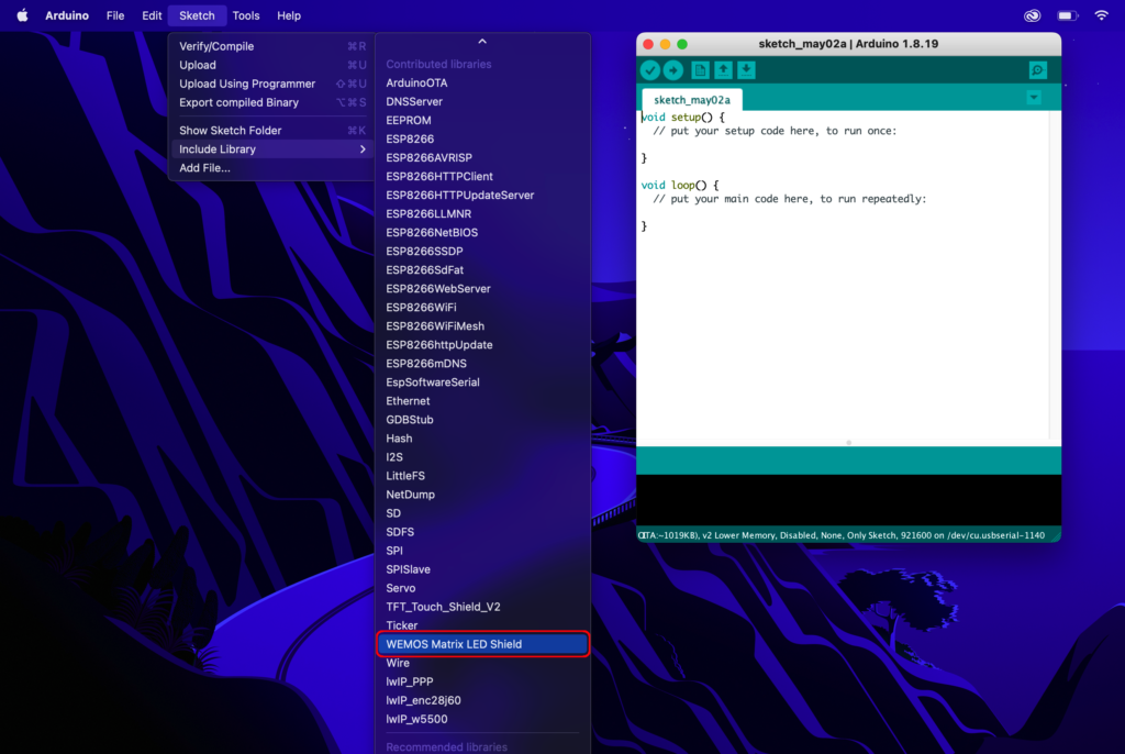
Next, open the Arduino IDE and click Sketch > Include Library > Add ZIP Library…
Select the downloaded Wemos Matrix LED Library ZIP file and click choose in order to add the library. You should now see the library available in the list of available libraries, as shown in the following screenshot.
How To Use The Wemos Matrix LED Library
Now that we have the Wemos Matrix LED library installed and the hardware prepared, we can finally begin to use it!
The following example will illuminate an LED at random, a nice little test for the LED matrix display. We can begin with a new sketch…
void setup() {
  // put your setup code here, to run once:

}

void loop() {
  // put your main code here, to run repeatedly:

}
Next we can select WEMOS Matrix LED Shield from the Sketch > Include Library menu in order to add the code to include the library. Alternatively we can just type it out manually.
#include <WEMOS_Matrix_LED.h>

void setup() {
  // put your setup code here, to run once:

}

void loop() {
  // put your main code here, to run repeatedly:

}
Next, we can add a line of code to initialise an instance of MLED with desired intensity. Here we also create a couple of variables to hold randomly generated numbers for the X and Y coordinates.
#include <WEMOS_Matrix_LED.h>

MLED mled(5); //set intensity to 5
int randX, randY;

void setup() {
  // put your setup code here, to run once:

}

void loop() {
  // put your main code here, to run repeatedly:

}
In our void setup() we will add the randomSeed() function. This is a pseudo-random number generator that uses a very long string of numbers to give the effect of randomly generating a number.
The value passed to the randomSeed() function is the starting point within the sequence. Using analogRead here randomises the point in which the sequence begins each time the sketch is started.
For further explanation of how the randomSeed() function works, check out the description on the Arduino site.
#include <WEMOS_Matrix_LED.h>

MLED mled(5); //set intensity=5
int randX, randY;

void setup() {
  // put your setup code here, to run once:
  randomSeed(analogRead(0));

}

void loop() {
  // put your main code here, to run repeatedly:

}
The first instruction in our void loop() will be to use the randomSeed() function to load random numbers into the variables we created for the X and Y coordinates.
The value passed to the random() function specifies the maximum. In this case the value generated will be between 0 and 7.
#include <WEMOS_Matrix_LED.h>

MLED mled(5); //set intensity=5
int randX, randY;

void setup() {
  // put your setup code here, to run once:
  randomSeed(analogRead(0));

}

void loop() {
  // put your main code here, to run repeatedly:
  randX = random(8);
  randY = random(8);

}
The next lines lines of code draw the dot at the position using the randomly generated coordinates. After the dot is drawn there is a short delay.
#include <WEMOS_Matrix_LED.h>

MLED mled(5); //set intensity=5
int randX, randY;

void setup() {
  // put your setup code here, to run once:
  randomSeed(analogRead(0));

}

void loop() {
  // put your main code here, to run repeatedly:
  randX = random(8);
  randY = random(8);

  // draw the dot
  mled.dot(randX,randY);
  mled.display();
  delay(200);

}
Finally the last few lines clear the dot and again there is a short delay.
#include <WEMOS_Matrix_LED.h>

MLED mled(5); //set intensity=5
int randX, randY;

void setup() {
  // put your setup code here, to run once:
  randomSeed(analogRead(0));

}

void loop() {
  // put your main code here, to run repeatedly:
  randX = random(8);
  randY = random(8);

  // draw the dot
  mled.dot(randX,randY);
  mled.display();
  delay(200);

  // clear the dot
  mled.dot(randX,randY,0);//clear dot
  mled.display();
  delay(200);
}
That’s it! Go ahead and compile the code and upload it onto the board, you should see the LED matrix flash single LEDs in a random pattern, very cool!
What Else Can The Wemos Matrix LED Do?
There is another sketch bundled with the Wemos Matrix LED library. This sketch cycles through some different intensities to demonstrate the capability, go ahead and give it a try!
#include <WEMOS_Matrix_LED.h>

MLED mled(0); //set intensity=0

void setup() {
  Serial.begin(115200);
  for(int i=0; i<8; i++)
  {
    mled.disBuffer[i]=0xff;  //full screen
  }


}

void loop() {

  for(int i=0;i<8;i++){
    mled.intensity=i;//change intensity
    mled.display();
    delay(1000);
  }
}
This next example code sequentially illuminates each LED until the whole matrix is illuminated.
#include <WEMOS_Matrix_LED.h>

MLED mled(5); //set intensity=5

void setup()
{

}

void loop() {

  for(int y=0;y<8;y++)
  {
    for(int x=0;x<8;x++)
    {
        mled.dot(x,y); // draw dot
        mled.display();
        delay(200);
    }
  }
}
This code example begins by illuminating all of the LEDs on the outside of the matrix and proceeds to illuminate them inward until all are illuminated, very cool!
#include <WEMOS_Matrix_LED.h>
MLED mled(5); //set intensity=5
void setup()
{
}
void loop(){

  //outside lines
  for(int x=0;x<8;x++){
    mled.dot(x,0); // draw dot
    mled.dot(x,7); // draw dot
    mled.display();
   }
  for(int y=0;y<8;y++){
    mled.dot(0,y); // draw dot
    mled.dot(7,y); // draw dot
    mled.display();
  }

  //inside lines
  delay(500);
  for(int x=1;x<7;x++){
    mled.dot(x,1); // draw dot
    mled.dot(x,6); // draw dot
    mled.display();
  }
  for(int y=1;y<7;y++){
    mled.dot(1,y); // draw dot
    mled.dot(6,y); // draw dot
    mled.display();
  }

  //inside lines 2
  delay(500);
  for(int x=2;x<6;x++){
    mled.dot(x,2); // draw dot
    mled.dot(x,5); // draw dot
    mled.display();
  }
  for(int y=2;y<6;y++){
    mled.dot(2,y); // draw dot
    mled.dot(5,y); // draw dot
    mled.display();
  }
  delay(500);

  //middle dot
  mled.dot(3,3); // draw dot
  mled.dot(3,4); // draw dot
  mled.dot(4,3); // draw dot
  mled.dot(4,4); // draw dot
  mled.display();
  delay(2000);
  for(int y=0;y<8;y++){
    for(int x=0;x<8;x++){
      mled.dot(x,y,0);//clear dot
      mled.display();
    }
  }
}
Conclusion
The Wemos Matrix LED Shield is a very cool little project that is very easy to build and program!
The examples here just show the very basics of the library and what is possible. Now that you have completed this tutorial you should have enough information to go build your own awesome LED Matrix project.
Perhaps combine the Matrix shield with the WiFi power of the ESP8266 and get your Wemos connected to WiFi, you can check out how to do that in this tutorial!
Thanks so much for visiting my site! If this article helped you achieve your goal and you want to say thanks, you can now support my work by buying me a coffee. I promise I won't spend it on beer instead... 😏