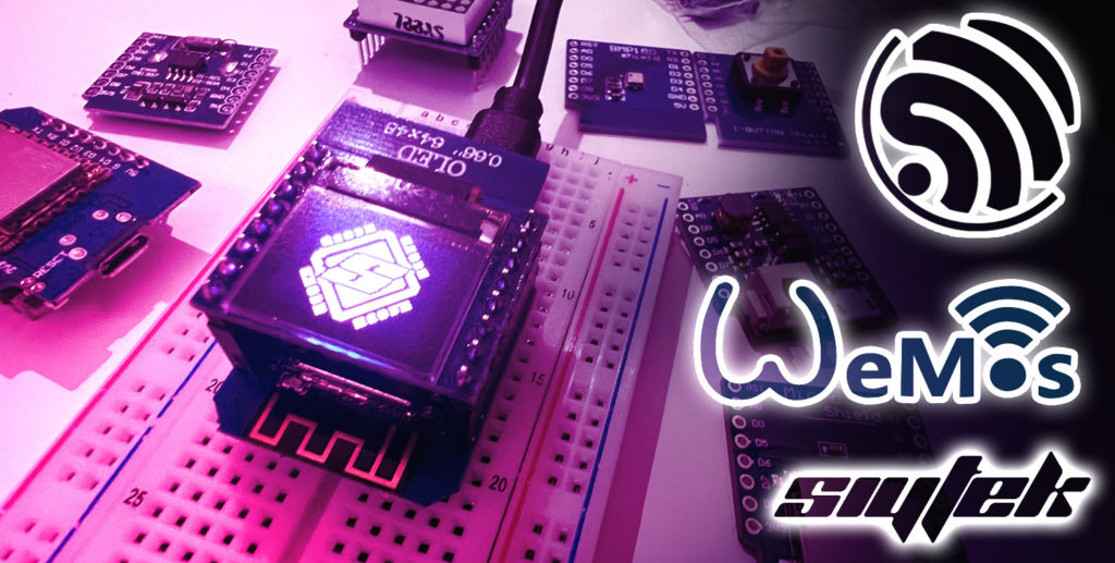
Let’s talk about one of the coolest shields for the D1 Mini, which won’t cost you a fortune either… the OLED 64×48 Shield!
In the previous article we talked about the Wemos D1 Mini Matrix LED shield and how it was a great shield to work with because of the striking results that it can produce. Well, we can say the same about the OLED shield too!
The Wemos OLED shield uses a 64×48 pixel monochrome OLED display that connects to the Wemos D1 Mini via pins D1 and D2, which double up as the I2C serial data and clock.
It makes use of the Adafruit SSD1306 library for Arduino, so it is very easy to program. We will cover all of the necessary setup in this article, so let’s get into it!
Table of Contents
- Prerequisite
- How Does The Wemos OLED Shield Work?
- How To Install The Wemos OLED Shield Library
- How To Use The Wemos OLED Shield Library
- Conclusion
Prerequisite
In order to follow this tutorial you will need a few things to get started. If you are completely new to the Wemos D1 Mini then I would recommend first checking out this guide.
You will need the following:
- A Wemos D1 Mini board
- A Wemos OLED Shield shield
- Soldering iron and some solder (to attach the pin header, if necessary)
- A USB-A to Micro-B cable
First you should install the Arduino IDE and set up the Wemos D1 Mini board, in order to be able to program the D1 Mini. You may also need to solder the headers on to both the Wemos D1 Mini and OLED shield.
If you are new to soldering headers onto these boards then don’t worry! It really is quite simple. The following video gives a good explanation showing how to do this, so take a minute to check it out:
Once you have soldered on the headers, plug the matrix shield into the main D1 Mini board and you are good to go!
How Does The Wemos OLED Shield Work?
The Wemos OLED shield consists of a 64 by 48 pixel OLED display that can communicate with the host by using the I2C serial bus.
The following screenshot shows the schematic diagram for the shield. It looks a little complicated but it is actually quite simple.
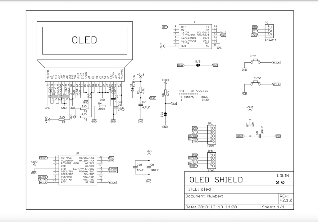
The official version of the shield has two additional buttons on either side, just under the display. These buttons are not present on all versions of the shield, including my cloned one.
Key 1 and Key 2 in the schematic connect to U2, which converts the button press into an I2C signal. Much of the circuitry in the schematic supports these additional two buttons.
The display itself its connected to some passive components that are required in order for it to function. However the simplicity in this shield can be seen when observing P1, the Wemos D1 Mini itself.
There are just two connections for the serial clock and data lines of the I2C bus, SCL and SDA respectively.
There is also a jumper, SJ1, that allows the I2C address to be chosen. By default it is set to 0x3C and in most cases this will work just fine.
How To Install The Wemos OLED Shield Library
So hopefully the schematic helps to clarify how the OLED shield works. Don’t worry if it is a little confusing, the only thing we really need to understand is that the OLED display connects to the Wemos D1 Mini using I2C.
This means that we simply need to install the correct libraries in Arduino. These libraries will handle all of the communication between the OLED display and the ESP8266 on the Wemos D1 Mini.
The libraries we need to include are as follows:
#include <SPI.h>
#include <Wire.h>
#include <Adafruit_GFX.h>
#include <Adafruit_SSD1306.h>
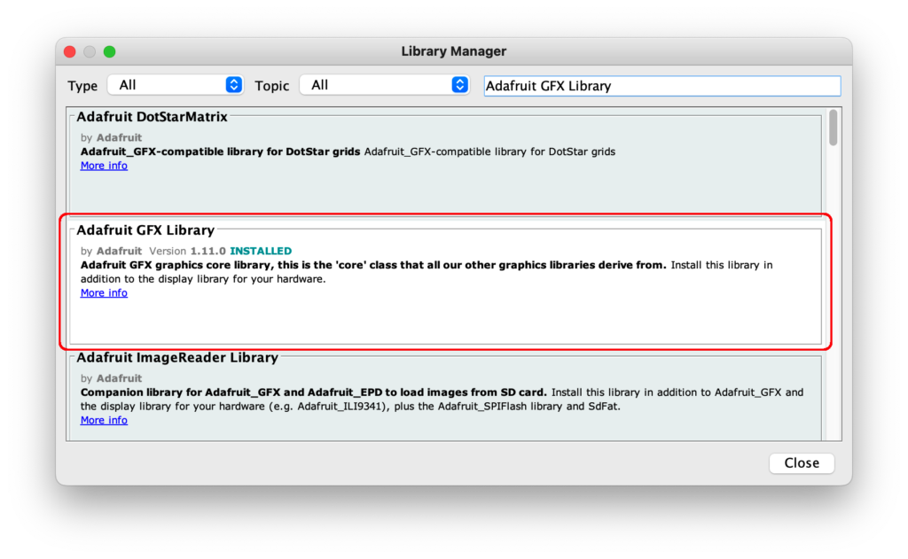
The SPI and Wire libraries will be installed by default. The Adafruit GFX and SSD1306 libraries are available via the library manager:
First, open the Arduino IDE. Then click Tools > Manage Libraries. Use the search function to locate the GFX library and click install.
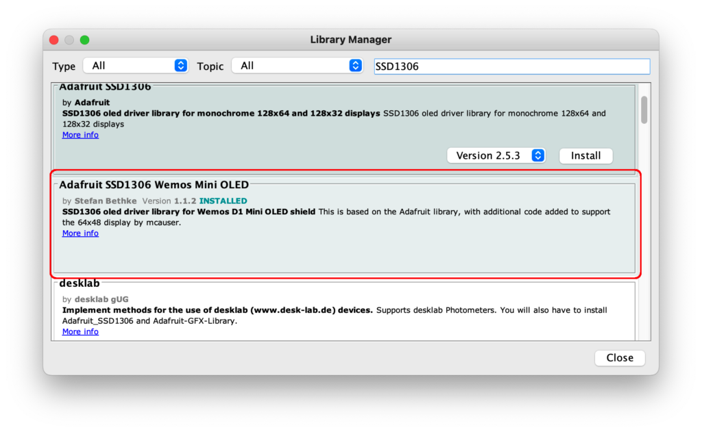
When locating the SSD1306 library, be sure to choose the Wemos compatible option in order to get the support for the 64×48 pixel display used on the shield.
How To Use The Wemos OLED Shield Library
Now that we have the libraries installed, we can take a look at getting this OLED display up and running!
For this sample project we will convert an image into an Arduino program and display it on the OLED display. As we will be converting it to 2-bit monochrome colour and a small resolution, it is best to use simple images such a logo.
Converting The Image For OLED
For demonstration purposes I will be using the logo from this website, but you can choose any image you want.
Once you have your image ready to go, we can convert it to Arduino code using the image2cpp tool. Head on over to http://javl.github.io/image2cpp/ and select your chosen image.
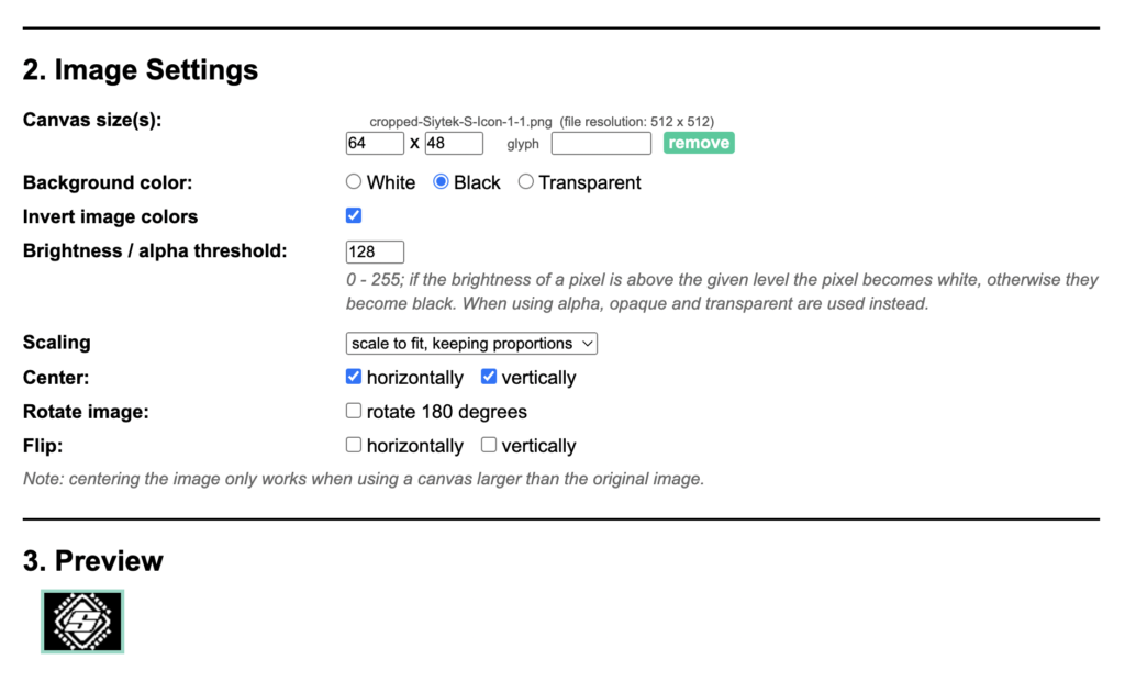
For canvas size choose 64 x 48 pixels in size to match the display size on the Wemos D1 Mini.
The background color and invert image colors are just personal preference, select them as you prefer.
The Brightness / alpha threshold determines the threshold in which the algorithm chooses a white or black pixel based upon the original pixel value.
If your image is basic and with good contrast the default value should work well. You can change this value with some trial and error to achieve the desired result.
For scaling the scale to fit option will probably work best. You can also choose to center, flip or rotate your image if desired.
In section 3 you will see a cool little preview of how your image is going to look on the OLED, awesome!
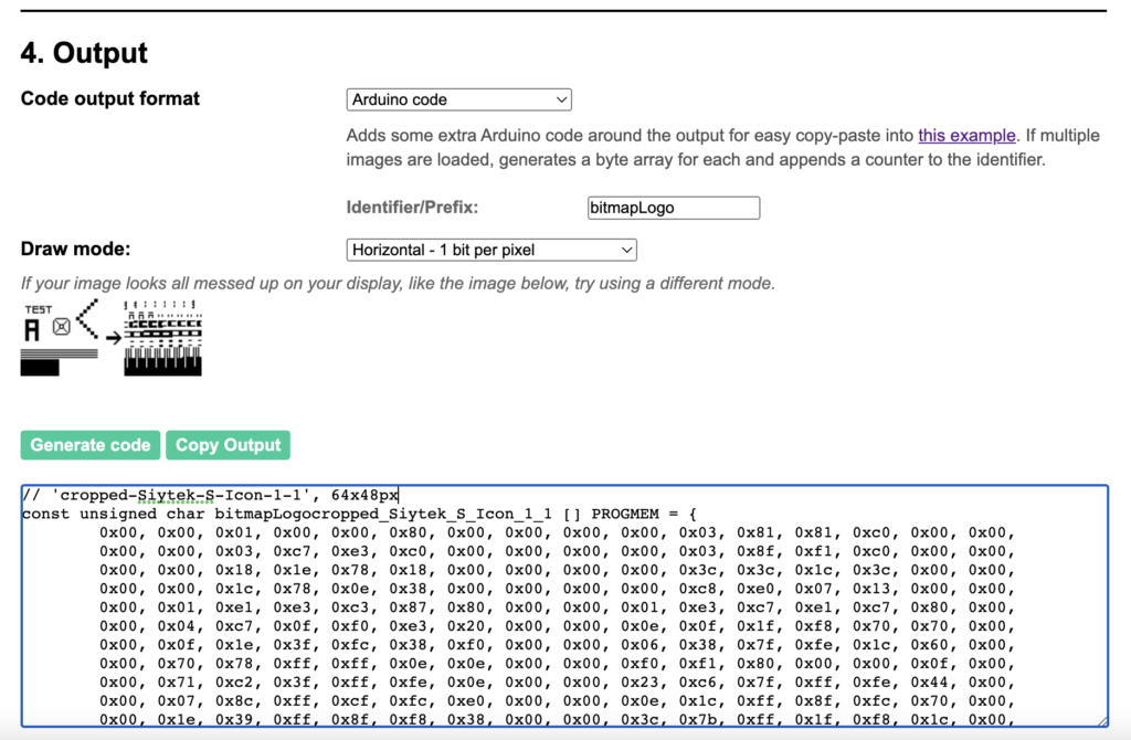
Generating The Code
Once you have all of the settings in place and the image looks desirable you can output the code. Leave the code output format set to Arduino code and set the identifier/Prefix to bitmapLogo.
Click generate code and the box beneath will be populated with code that can be pasted into Arduino. Leave this code to one side for now, we will use it later.
Programming The Wemos D1 Mini To Display An Image On An OLED Display
Go ahead and open up a new project in the Arduino IDE. If you have never programmed a Wemos D1 Mini before with the Arduino IDE then I would suggest checking this out first.
// Paste your bitmap here

void setup() {
  // put your setup code here, to run once:

}

void loop() {
  // put your main code here, to run repeatedly:

}
First, let’s add the dependencies and configuration for the display. For the Wemos D1 Mini the OLED_RESET pin should be defined as 0.
#include <SPI.h>
#include <Wire.h>
#include <Adafruit_GFX.h>
#include <Adafruit_SSD1306.h>

#define OLED_RESET 0
Adafruit_SSD1306 display(OLED_RESET);

// Paste your bitmap here

void setup() {
  // put your setup code here, to run once:

}

void loop() {
  // put your main code here, to run repeatedly:

}
Next we can add some code to the setup. We will use the display.begin function to begin the display using I2C address 0x3C. This should match the address on the OLED shield. If in doubt the default 0x3C should work fine.
Next we will add the display.clearDisplay() function in order to blank the screen.
#include <SPI.h>
#include <Wire.h>
#include <Adafruit_GFX.h>
#include <Adafruit_SSD1306.h>

#define OLED_RESET 0
Adafruit_SSD1306 display(OLED_RESET);

// Paste your bitmap here

void setup() {
  // put your setup code here, to run once:
  display.begin(SSD1306_SWITCHCAPVCC, 0x3C); //or 0x3C
  display.clearDisplay(); // for Clearing the display
  display.display();
}

void loop() {
  // put your main code here, to run repeatedly:

}
After we have cleared the screen we will display the image that we converted earlier.
You should replace bitmapLogocropped_Siytek_S_Icon_1_1 with your own file name generated in the earlier step.
#include <SPI.h>
#include <Wire.h>
#include <Adafruit_GFX.h>
#include <Adafruit_SSD1306.h>

#define OLED_RESET 0
Adafruit_SSD1306 display(OLED_RESET);

// Paste your bitmap here

void setup() {
  // put your setup code here, to run once:
  display.begin(SSD1306_SWITCHCAPVCC, 0x3C); //or 0x3C
  display.clearDisplay(); // for Clearing the display
  // display.drawBitmap(x position, y position, bitmap data, bitmap width, bitmap height, color)
  display.drawBitmap(0, 0, bitmapLogocropped_Siytek_S_Icon_1_1, 64, 48, WHITE);
  display.display();
}

void loop() {
  // put your main code here, to run repeatedly:

}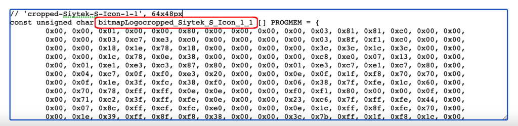
Lastly you should copy all of the code generated earlier and paste it into the relevant section just beneath the // Paste your bitmap here note.
#include <SPI.h>
#include <Wire.h>
#include <Adafruit_GFX.h>
#include <Adafruit_SSD1306.h>
#define OLED_RESET 0
Adafruit_SSD1306 display(OLED_RESET);
// Paste your bitmap here
// 'cropped-Siytek-S-Icon-1-1', 64x48px
const unsigned char bitmapLogocropped_Siytek_S_Icon_1_1 [] PROGMEM = {
0x00, 0x00, 0x01, 0x00, 0x00, 0x80, 0x00, 0x00, 0x00, 0x00, 0x03, 0x81, 0x81, 0xc0, 0x00, 0x00,
0x00, 0x00, 0x03, 0xc7, 0xe3, 0xc0, 0x00, 0x00, 0x00, 0x00, 0x03, 0x8f, 0xf1, 0xc0, 0x00, 0x00,
0x00, 0x00, 0x18, 0x1e, 0x78, 0x18, 0x00, 0x00, 0x00, 0x00, 0x3c, 0x3c, 0x1c, 0x3c, 0x00, 0x00,
0x00, 0x00, 0x1c, 0x78, 0x0e, 0x38, 0x00, 0x00, 0x00, 0x00, 0xc8, 0xe0, 0x07, 0x13, 0x00, 0x00,
0x00, 0x01, 0xe1, 0xe3, 0xc3, 0x87, 0x80, 0x00, 0x00, 0x01, 0xe3, 0xc7, 0xe1, 0xc7, 0x80, 0x00,
0x00, 0x04, 0xc7, 0x0f, 0xf0, 0xe3, 0x20, 0x00, 0x00, 0x0e, 0x0f, 0x1f, 0xf8, 0x70, 0x70, 0x00,
0x00, 0x0f, 0x1e, 0x3f, 0xfc, 0x38, 0xf0, 0x00, 0x00, 0x06, 0x38, 0x7f, 0xfe, 0x1c, 0x60, 0x00,
0x00, 0x70, 0x78, 0xff, 0xff, 0x0e, 0x0e, 0x00, 0x00, 0xf0, 0xf1, 0x80, 0x00, 0x00, 0x0f, 0x00,
0x00, 0x71, 0xc2, 0x3f, 0xff, 0xfe, 0x0e, 0x00, 0x00, 0x23, 0xc6, 0x7f, 0xff, 0xfe, 0x44, 0x00,
0x00, 0x07, 0x8c, 0xff, 0xcf, 0xfc, 0xe0, 0x00, 0x00, 0x0e, 0x1c, 0xff, 0x8f, 0xfc, 0x70, 0x00,
0x00, 0x1e, 0x39, 0xff, 0x8f, 0xf8, 0x38, 0x00, 0x00, 0x3c, 0x7b, 0xff, 0x1f, 0xf8, 0x1c, 0x00,
0x00, 0x38, 0xf3, 0xff, 0x00, 0x03, 0x1e, 0x00, 0x00, 0x70, 0xf7, 0xff, 0xff, 0xe7, 0x0e, 0x00,
0x00, 0x70, 0xe7, 0xff, 0xff, 0xe7, 0x8e, 0x00, 0x00, 0x38, 0xe0, 0x00, 0xff, 0xcf, 0x1e, 0x00,
0x00, 0x38, 0x4f, 0xf8, 0xff, 0xce, 0x1c, 0x00, 0x00, 0x1c, 0x1f, 0xf9, 0xff, 0x9c, 0x3c, 0x00,
0x00, 0x0e, 0x3f, 0xf1, 0xff, 0x98, 0x70, 0x00, 0x00, 0x07, 0x3f, 0xf3, 0xff, 0x30, 0xe0, 0x00,
0x00, 0x22, 0x7f, 0xff, 0xff, 0x21, 0xe4, 0x00, 0x00, 0x70, 0x7f, 0xff, 0xfc, 0x43, 0x8e, 0x00,
0x00, 0xf0, 0x00, 0x00, 0x00, 0x87, 0x0f, 0x00, 0x00, 0x70, 0x70, 0x7f, 0xff, 0x0f, 0x0e, 0x00,
0x00, 0x06, 0x38, 0x7f, 0xfe, 0x1c, 0x60, 0x00, 0x00, 0x0f, 0x1c, 0x3f, 0xfc, 0x38, 0xf0, 0x00,
0x00, 0x0e, 0x0e, 0x1f, 0xf8, 0x78, 0x70, 0x00, 0x00, 0x04, 0xc7, 0x0f, 0xf0, 0xe3, 0x20, 0x00,
0x00, 0x01, 0xe3, 0x87, 0xe1, 0xc7, 0x80, 0x00, 0x00, 0x01, 0xe1, 0xc3, 0xc3, 0xc7, 0x80, 0x00,
0x00, 0x00, 0xc8, 0xe0, 0x07, 0x13, 0x00, 0x00, 0x00, 0x00, 0x1c, 0x70, 0x0e, 0x38, 0x00, 0x00,
0x00, 0x00, 0x3c, 0x38, 0x1e, 0x3c, 0x00, 0x00, 0x00, 0x00, 0x18, 0x1e, 0x78, 0x18, 0x00, 0x00,
0x00, 0x00, 0x03, 0x8f, 0xf1, 0xc0, 0x00, 0x00, 0x00, 0x00, 0x03, 0xc7, 0xf3, 0xc0, 0x00, 0x00,
0x00, 0x00, 0x03, 0x81, 0x81, 0xc0, 0x00, 0x00, 0x00, 0x00, 0x01, 0x00, 0x00, 0x80, 0x00, 0x00
};
// Array of all bitmaps for convenience. (Total bytes used to store images in PROGMEM = 400)
const int bitmapLogoallArray_LEN = 1;
const unsigned char* bitmapLogoallArray[1] = {
bitmapLogocropped_Siytek_S_Icon_1_1
};
void setup() {
// put your setup code here, to run once:
display.begin(SSD1306_SWITCHCAPVCC, 0x3C); //or 0x3C
display.clearDisplay(); // for Clearing the display
// display.drawBitmap(x position, y position, bitmap data, bitmap width, bitmap height, color)
display.drawBitmap(0, 0, bitmapLogocropped_Siytek_S_Icon_1_1, 64, 48, WHITE);
display.display();
}
void loop() {
// put your main code here, to run repeatedly:
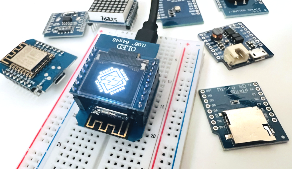
}Now you can go ahead and compile and upload your code! The end result should be your image displayed on the Wemos OLED shield, how cool!
Conclusion
The Wemos OLED Shield is a very cool addition to the Wemos ecosphere and looks totally cool when loaded with a custom image!
The examples here just show the very basics of the library and what is possible. Now that you have completed this tutorial you should have enough information to go build your own awesome OLED project.
Perhaps combine the OLED shield with the WiFi power of the ESP8266 and get your Wemos connected to WiFi, you can check out how to do that in this tutorial!
Alternatively if you enjoyed the topic of LED display, go ahead and check out the LED Matrix Shield tutorial!
Thanks so much for visiting my site! If this article helped you achieve your goal and you want to say thanks, you can now support my work by buying me a coffee. I promise I won't spend it on beer instead... 😏


“It should look something like this.”
No, it should not. It’s plugged in the wrong way in the first picture. Unfortunately I was too lazy to check it myself and toasted my OLED.
Hi Chris, apologies about the confusion, I have removed the image that you mentioned. Seems I was also too lazy to check my post properly before publishing, so I guess we both just learned the importance of checking our work thoroughly!
Thanks for fixing the image. Turns out my OLED isn’t toasted. I ordered a new WEMOS D1 Mini and a new OLED shield and it behaves the same way. Apparently some magic is missing. Either the 0x3C address selector pad need to be soldered (will try that this evening) or there is some quirk with using PlatformIO instead of the Arduino IDE. I’ll figure that out.
I figured it out. The symptom was that the LED showed random pixels but could not be controlled. The issue happened both in Arduino IDE and PlatformIO. That effect happens if you have the “normal” SSD1306 library installed as well as the library “Adafruit SSD1306 Wemos Mini OLED” recommended here. My IDE chose the “normal” library which messed up the display. It is important to remove the “normal” library thoroughly.
The correct library comes with an example containing these three helpful lines:
#if (SSD1306_LCDHEIGHT != 48)
#error(“Height incorrect, please fix Adafruit_SSD1306.h!”);
#endif
If you get that error then you still have the “normal” library installed. I am a bit disappointed that PlatformIO chose the right library in the project’s platformio.ini:
lib_deps =
stblassitude/Adafruit SSD1306 Wemos Mini OLED@^1.1.2
adafruit/Adafruit GFX Library@^1.11.5
…but it was still taking the wrong library that was installed. I hope this helps other who might be frustrated and think they have a broken OLED.
Ahh, well that is good news Chris and glad my error didn’t cause you to nuke an OLED! 🙂 looking again I see that connecting the OLED in reverse would connect GND to the ADC pin. So I guess although 5V would be tied to 3V3 through the reset pullup resistor, the lack of a GND connection probably saves it from burning.
Still good to have removed that image as it could certainly be confusing for the readers here. Well done for figuring it out and thank you for sharing your findings, it could certainly benefit others who may encounter this issue.