
Looking to integrate a servo with Home Assistant?
This step-by-step tutorial will guide you through the process of building a wireless servo and integrating it with Home Assistant!
For the example we will be using a readily available Wemos D1 Mini and RC servo, however you can use any compatible ESP device and servo.
By utilizing an ESP device and the ESPHome platform, adding a servo to your smart home is a piece of cake!
Table of Contents
- Prerequisite
- Wiring
- Configure ESPHome
- Configure Home Assistant
- Add to the UI and Test the servo
- Adding multiple servos
- Conclusion
Prerequisite
For this tutorial we will assume that you have Home Assistant up and running already.
A very basic knowledge of configuration.yaml would also be advantageous, but we will cover as much detail as possible.
If you are completely new to Home Assistant then you should probably first check out my beginners guide to YAML, as well as my tutorials on automation and scripts.
You will also need to configure the ESPHome add-on in Home Assistant and have a compatible ESP device such as the Wemos D1 Mini.
If you haven’t installed the ESP Home add-on yet, go ahead and check out my tutorial on how to add ESPHome to Home Assistant.
Wiring
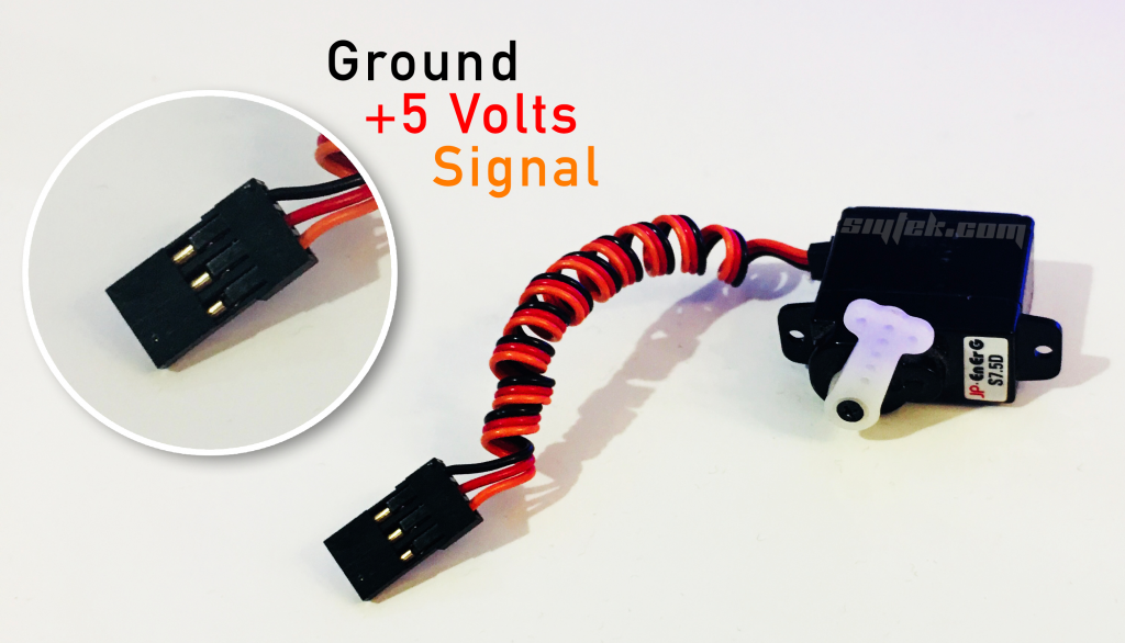
A standard analogue RC servo usually has three wires and operates from 5 volts.
The red and black wire should be connected to +5V and ground respectively. The third lead is the control signal and is usually yellow or orange.
Servos are usually shipped with some variant of a standard pin header style connection with 2.54mm pin spacing.
For testing you can connect the servo to the ESP device using jumper wires.
The red positive lead is usually connected to the middle pin of the connector to prevent damage occurring if the connecter is inserted backwards.
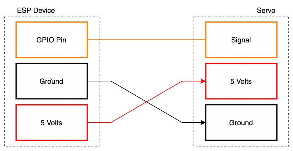
As we are not connecting our RC servo to a standard RC receive, we need to take care that the connections are correct.
On our ESP device we need to connect the orange signal lead to one of the GPIOs. For this example I will connect the signal lead to D3 on the Wemos D1 Mini.
If you are using a different device and/or choose a different pin, don’t forget to amend the example code as necessary.
The black lead needs to be connected to ground, labelled as ‘G’ on the Wemos D1 Mini.
The red lead needs to be connected to 5 volts, labeled as ‘5V’ on the Wemos D1 Mini.
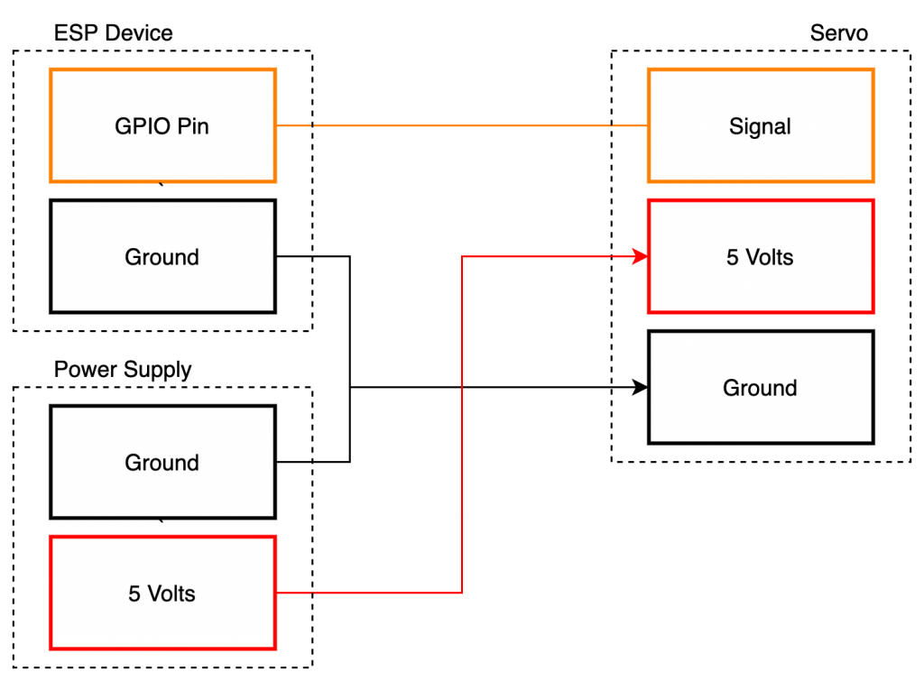
Note that larger servos and/or servos under a lot of load may draw more current than the USB port can supply.
If in doubt you should use an external 5 volt power supply.
If you are using an external power supply, the +5V connection should be made to the power supply and the ground terminals should be tied together.
The signal lead should be connected as normal, between the ESP device and servo.
Configure ESPHome
So now hopefully you have a servo connected to an ESP device as we are ready to start the configuration!
As previously mentioned you will need to have the ESPHome add-on installed in Home Assistant. Alternatively you can write your configurations with a text editor and upload them manually.
Create a device
First you should add a new device in ESPHome if you have not done so already.
When your new device is available in the user interface, go ahead and click edit and you should be presented with something like the following template.
Note that the parameters will reflect your device configuration.
esphome:
  name: little_wemos
  platform: ESP8266
  board: d1_mini

wifi:
  ssid: "MyWiFiRouter"
  password: "************"

  # Enable fallback hotspot (captive portal) in case wifi connection fails
  ap:
    ssid: "Little Wemos Fallback Hotspot"
    password: "************"

captive_portal:

# Enable logging
logger:

api:

ota:
Add the PWM output
First we will add an output component that tells ESPHome to send data to our servo.
As our servo requires a PWM signal for control we will use the esp8266_pwm platform. Note that you should change this if you are using an ESP32 board.
We need to specify the output pin that the servo’s signal lead is connected to. I am using pin D4 (GPIO02) but you should change this accordingly if you are using a different pin or device.
We also need to specify a PWM frequency of 50 Hz. We will give this output the ID pwm_output, which will be used to receive the data.
esphome:
  name: little_wemos
  platform: ESP8266
  board: d1_mini

wifi:
  ssid: "MyWiFiRouter"
  password: "************"

  # Enable fallback hotspot (captive portal) in case wifi connection fails
  ap:
    ssid: "Little Wemos Fallback Hotspot"
    password: "************"

captive_portal:

# Enable logging
logger:

api:

ota:

output:
  - platform: esp8266_pwm
    id: pwm_output
    pin: D3
    frequency: 50 Hz
Add the servo component
Next we will add the servo component. This will act as the link between the output component that we just created and the incoming data from Home Assistant.
We will specify the output attribute as pwm_output in order to pass the data to the output.
We will also assign the ID attribute my_servo, which will be used to receive the data from Home Assistant.
esphome:
  name: little_wemos
  platform: ESP8266
  board: d1_mini

wifi:
  ssid: "MyWiFiRouter"
  password: "************"

  # Enable fallback hotspot (captive portal) in case wifi connection fails
  ap:
    ssid: "Little Wemos Fallback Hotspot"
    password: "************"

captive_portal:

# Enable logging
logger:

api:

ota:

output:
  - platform: esp8266_pwm
    id: pwm_output
    pin: D3
    frequency: 50 Hz

servo:
  - id: my_servo
    output: pwm_output
Add the native API component
At the time of writing Home Assistant does not yet support the servo component directly (version 0.108). Therefore in order to communicate with Home Assistant we must set up the native API component in ESPHome.
The native API component is used to directly receive data from Home Assistant and it will allow us to create a custom service. We will then be able to reference the custom service in the Home Assistant setup.
Data will be passed from the custom service in Home Assistant to the native API component. It will then be passed from the native API to the output pin via the servo component.

First we will add a service under the api component and name it control_servo. We will also create a new float variable to store the value for the servo named level.
esphome:
  name: little_wemos
  platform: ESP8266
  board: d1_mini

wifi:
  ssid: "MyWiFiRouter"
  password: "************"

  # Enable fallback hotspot (captive portal) in case wifi connection fails
  ap:
    ssid: "Little Wemos Fallback Hotspot"
    password: "************"

captive_portal:

# Enable logging
logger:

api:
  services:
    - service: control_servo
      variables:
        level: float

ota:

output:
  - platform: esp8266_pwm
    id: pwm_output
    pin: D3
    frequency: 50 Hz

servo:
  - id: my_servo
    output: pwm_output
Home Assistant will create a custom service named esphome.<your-device>_control_servo and the data will be passed from this service to the variable level within the ESPHome device.
Next we will write the value level to the servo component that we created earlier, named my_servo.
esphome:
  name: little_wemos
  platform: ESP8266
  board: d1_mini

wifi:
  ssid: "MyWiFiRouter"
  password: "************"

  # Enable fallback hotspot (captive portal) in case wifi connection fails
  ap:
    ssid: "Little Wemos Fallback Hotspot"
    password: "************"

captive_portal:

# Enable logging
logger:

api:
  services:
    - service: control_servo
      variables:
        level: float
      then:
        - servo.write:
            id: my_servo
            level: !lambda 'return level / 100.0;'

ota:

output:
  - platform: esp8266_pwm
    id: pwm_output
    pin: D3
    frequency: 50 Hz

servo:
  - id: my_servo
    output: pwm_output
That completes the ESPHome configuration! Now you can go ahead and upload the code to your device.
Configure Home Assistant
Next we will configure Home Assistant by adding an automation to control to servo.
For this example we will link the automation to a slider on the user interface, but you can adapt the code to something more suited to your own application.
Add an input
Firstly we need to create a way to input a value in Home Assistant to send to our servo.
We will do this by adding a simple slider that will control the movement of the servo.
In order to add a slider we will create a new instance of input_number in the configuration.yaml file called servo_control.
We will give it minimum and maximum values of -100 and 100 respectively. We will also set the initial value to 0 and step value to 1.
input_number:
  servo_control:
    initial: 0
    min: -100
    max: 100
    step: 1
    mode: slider
Add automation
In order to link our slider to the ESPHome device we need to create a new automation instance in the configuration.yaml file.
The entity for the trigger should be set to the slider entity that we just created. The action will then be fired whenever the slider changes value.
In the action section we will set the service to our ESPHome custom service created by the native API.
You will find this in your list of services as esphome.<your-device>_control_servo.
In order to push the value from the slider to the native API via the service, we will use a data template.
This template fetches the value of the slider and puts it into our level variable within ESPHome.
automation:
  - alias: Write Servo Value to ESP
    trigger:
      platform: state
      entity_id: input_number.servo_control
    action:
      - service: esphome.little_wemos_control_servo
        data_template:
          level: '{{ trigger.to_state.state | int }}'
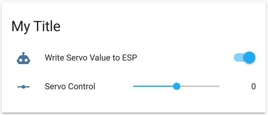
Add to the UI and Test the servo
Now we are ready to give the servo a test! Go ahead and add input_number.servo_control to the user interface.
You can add the switch for the automation too, if you would like the option to disable the servo movement.
Adding multiple servos
If multiple servos are needed, we can simply replicate each stage of the code using a unique name. Let’s add a second servo and call it servo2, first we will add it to ESPHome.
Second servo in ESPHome
First we can add a second instance to the api communication.
We must differentiate the new servo by giving it a unique name. In this example I have simply called it servo2.
esphome:
  name: little_wemos
  platform: ESP8266
  board: d1_mini

wifi:
  ssid: "MyWiFiRouter"
  password: "************"

  # Enable fallback hotspot (captive portal) in case wifi connection fails
  ap:
    ssid: "Little Wemos Fallback Hotspot"
    password: "************"

captive_portal:

# Enable logging
logger:

api:
  services:
    - service: control_servo
      variables:
        level: float
      then:
        - servo.write:
            id: my_servo
            level: !lambda 'return level / 100.0;'
    - service: control_servo2
      variables:
        level: float
      then:
        - servo.write:
            id: my_servo2
            level: !lambda 'return level / 100.0;'

ota:

output:
  - platform: esp8266_pwm
    id: pwm_output
    pin: D3
    frequency: 50 Hz

servo:
  - id: my_servo
    output: pwm_output
Next we need to add a second PWM output. Here we can specify the pin that we wish to use for the second servo.
esphome:
  name: little_wemos
  platform: ESP8266
  board: d1_mini

wifi:
  ssid: "MyWiFiRouter"
  password: "************"

  # Enable fallback hotspot (captive portal) in case wifi connection fails
  ap:
    ssid: "Little Wemos Fallback Hotspot"
    password: "************"

captive_portal:

# Enable logging
logger:

api:
  services:
    - service: control_servo
      variables:
        level: float
      then:
        - servo.write:
            id: my_servo
            level: !lambda 'return level / 100.0;'
    - service: control_servo2
      variables:
        level: float
      then:
        - servo.write:
            id: my_servo2
            level: !lambda 'return level / 100.0;'

ota:

output:
  - platform: esp8266_pwm
    id: pwm_output
    pin: D3
    frequency: 50 Hz
  - platform: esp8266_pwm
    id: pwm_output2
    pin: D2
    frequency: 50 Hz

servo:
  - id: my_servo
    output: pwm_output
Finally we will add an instance for the second servo to tie the incoming data from the servo2 Home Assistant service to the physical PWM output.
esphome:
  name: little_wemos
  platform: ESP8266
  board: d1_mini

wifi:
  ssid: "MyWiFiRouter"
  password: "************"

  # Enable fallback hotspot (captive portal) in case wifi connection fails
  ap:
    ssid: "Little Wemos Fallback Hotspot"
    password: "************"

captive_portal:

# Enable logging
logger:

api:
  services:
    - service: control_servo
      variables:
        level: float
      then:
        - servo.write:
            id: my_servo
            level: !lambda 'return level / 100.0;'
    - service: control_servo2
      variables:
        level: float
      then:
        - servo.write:
            id: my_servo2
            level: !lambda 'return level / 100.0;'

ota:

output:
  - platform: esp8266_pwm
    id: pwm_output
    pin: D3
    frequency: 50 Hz
  - platform: esp8266_pwm
    id: pwm_output2
    pin: D2
    frequency: 50 Hz

servo:
  - id: my_servo
    output: pwm_output
  - id: my_servo2
    output: pwm_output2
Second servo in Home Assistant
Now we can add the second servo to our Home Assistant user interface. First let’s add a second input_number slider for controlling our second servo.
Again in this example I am simply naming it with a numerical sequence.
input_number:
servo_control:
name: Servo Control
initial: 0
min: -100
max: 100
step: 1
mode: slider
servo_control2:
name: Servo Control
initial: 0
min: -100
max: 100
step: 1
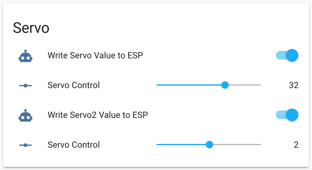
mode: sliderNow we can add a second automation. If you have configured ESPHome correctly, you should find a second service available in Home Assistant called esphome.<your-device-name>_control_servo2.
automation:
  - alias: Write Servo Value to ESP
    trigger:
      platform: state
      entity_id: input_number.servo_control
    action:
      - service: esphome.wemos_d1_mini_control_servo
        data_template:
          level: '{{ trigger.to_state.state | int }}'

  - alias: Write Servo2 Value to ESP
    trigger:
      platform: state
      entity_id: input_number.servo_control2
    action:
      - service: esphome.wemos_d1_mini_control_servo2
        data_template:
          level: '{{ trigger.to_state.state | int }}'
Finally we can add the slider and automation to the user interface in order to control the second servo. You can repeat this process in order to add even more servos. Awesome!
Conclusion
In this tutorial we learnt how to harness the power of ESPHome to make a bespoke integration within Home Assistant.
The ability to control servos adds many possibilities to the smart home ideas repertoire and could be further adapted for devices larger than an RC servo.
Why not go check out some of my other awesome Home Assistant tutorials to get some inspiration for your next ESPHome device!
Thanks so much for visiting my site! If this article helped you achieve your goal and you want to say thanks, you can now support my work by buying me a coffee. I promise I won't spend it on beer instead... 😏


Hello! Thanks for your perfect how to..
One question only, is it possible to control multiple servos? I am trying but no luck.. What part of the code needs to be added for a second servo?
Thanks in advance!
Hey Isidoros, thanks for visiting and commenting! Yes you certainly can control multiple servos, I have added a new section to the tutorial that explains how to do this. Hope it helps!
https://siytek.com/esphome-servo-example/#Adding_multiple_servos
Thanks one more time for your help!! It works great!
Your blog is very helpfull!! Keep up the perfect job!
Excellent! Very pleased it worked for you Isidoros and thanks again for visiting! 🙂
Hello,
Congratulations on the page!
Very didactic and easy to understand.
When will I write the level of value in the servo component
then:
– servo.write:
id: my_servo
level:! lambda ‘return level / 100.0;’
It gives the following error:
unknown tag! at line 29, column 51:
…! lambda ‘return level / 100.0;’
^
Any idea what I’m doing wrong?
I’ve done and reifz several times and it always gives this problem.
Thank you very much for your attention
Now compiled even giving error!
Hey Mateus, thanks for visiting! It looks like you have ‘!’ in the wrong place, it should be next to the lambda…
level:! lambda ‘return level / 100.0;’
change to…
level: !lambda ‘return level / 100.0;’
Thank you very much for your attention and quick response!
hi, nice tutorial, but why i can’t add the automation on the service esphome
it’s say : Failed to call service esphome/ultrasonic_control_servo. extra keys not allowed @ data[‘automation’]
ah, i found it, the action service should be my project name, but now my servo wouldn’t rotating
Hi Andrew, I would need some more info to help. Are you receiving any errors? Can you confirm that the servo works/have you tried it with a different servo? When I first set this up I could not get it to work for a while and it turned out that I was using a faulty servo! As soon as I swapped the servo, it worked fine. Are you supplying your servo with adequate power? A larger servo may require from an external power source.
Hi Siytek,
Nide . Your HA tutorials are helpful in my home automation project.
I need one help. I am using a stepper/ servo motor to control my camera to rotate and capture a 180 degree view . But I am facing an issue with my stepper motor where if power is switched off for the motor and then I move the input slider to different position, the stepper position does not recognize and when it comes up back then the whole things takes a different position all together making the camera view angle totally different.
Is there a way in servo motor (or stepper motor whichever is easier) where I can tell my motor to retain the position after boot according to my input slider in Home assistant.
Hi Vivek, thanks for visiting! Could you tell me more about your hardware? Are you using a stepper motor, or a servo?
Thanks so much for this! Had an error for a while but it was my own. Working perfectly now…just need a bigger servo.
Glad to be of service David, good luck with your bigger servo! 🙂
Hi! thank you for this tutorial very easy to understand for a noob like me.
But, where can i locate “configuration.yaml file called servo_control” ?
Is it the same /config/configuration.yaml ??
Hi! This works great! However the servo is always active. Is there a way to add a “switch” to espeasy to attach/detach servo? It’s easy to connect the servo power to a pin on the esp but this should be possible in software.
Keep up the good work!
Is there any relationship between “servo_control” (as used in the input section) and the service called “control_servo” (as referenced in the ESPHOME code)?
What is the relationship between these two – I thought it should be the same in both cases?
I’m pulling my hair out with this.
I’ve recreated the above instructions and keep getting an error.
‘The automation “Write Servo Value to ESP” (automation.write_servo_value_to_esp) has an action that calls an unknown service: esphome.little_wemos_control_servo’
Any advice on what I should check?
Try checking your services using developers tools, do a search for “esphome.” – what services do you see? You may also get some clues here: https://community.home-assistant.io/t/unexpected-service-call-check-for-automation-that-has-not-triggered/458257
Sorry that you are having trouble, this article is fairly outdated at the moment. I am travelling at the moment so don’t have access to an ESP nor servo to text/update the article, however it is on my list of articles to update asap! Thanks
Hi. Thank you for a great video. I just want to know if the set up and config would be the same for a Pi Pico W connected to a Servo ? Im having issues with this, but suspect it could be power related? Any pointers would be highly appreciated
Hi Pieter, yes I imagine the setup would be the same for the Pi Pico as they both use a 3V3 GPIO. The servo should be powered from its own 5V source, I don’t think the Pico has a 5V output anyway. Maybe put a current limiting resistor in series between the servo signal and GPIO, something like 10k should do it. If you have access to an oscilloscope, you can check if the PWM signal looks correct. More info about PWM here: https://siytek.com/how-does-led-dimming-work/#Duty-cycle
Hello Simon
Your template is great. I have a problem. Where do I put this?
#Servo_control
input_number:
servo_control:
initial: 0
min: -100
max: 100
step: 1
mode: slider
automation:
– alias: Write Servo Value to ESP
trigger:
platform: state
entity_id: input_number.servo_control
action:
– service: esphome.esphome-web-6659be_control_servo
data_template:
level: ‘{{ trigger.to_state.state | int }}’
In the configuration.yaml or to the automations?
Thanks a lot!!
Michael
whats the code for the automation to be able to have the switch above the slider?
This bit:
#Servo_control
input_number:
servo_control:
initial: 0
min: -100
max: 100
step: 1
mode: slider
goes in configeration.yaml
and this bit:
automation:
– alias: Write Servo Value to ESP
trigger:
platform: state
entity_id: input_number.servo_control
action:
– service: esphome.esphome-web-6659be_control_servo
data_template:
level: ‘{{ trigger.to_state.state | int }}’
Goes in automations. but i had errors for mine. found it easier to jsut make a new automation with the visual editor, and create it that way. than for the servie part, switch it to the yaml editor and copy the code he used