Any seasoned EAGLE enthusiast is sure to know about some of the quirks with the EAGLE user interface. One such quirk that is almost unavoidable is the inevitable inconsistency that can occur between the board and schematic files.
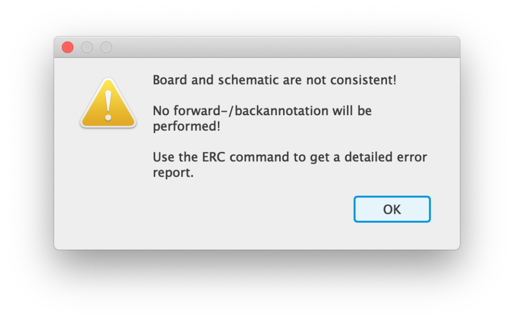
Even the most careful user can find themself encountering the dreaded board and schematic are not consistent error…
Why Are There Inconsistency Errors In EAGLE?
You only have to dig a little into the Autodesk EAGLE forums to find some heated comments from users who spent hours designing boards, only to lose those hours to inconsistency errors.
Those who entered the world of EAGLE and its quirks may not know that such workflows date back many years further than Autodesk, prior to the sale of EAGLE by its original developer, CADSoft.
It is not so simple for Autodesk to just correct this feature quickly, therefore it is important to understand what causes an inconsistency, the methods that can aid in fixing it and also how to avoid it in future.
Before continuing, I will assume that you are already using EAGLE with some competency. If not then you might want to check out my EAGLE beginners guide first.
What Causes A Board And Schematic Inconsistency in EAGLE?
An inconsistency error occurs when the .sch file and the .brd file become inconsistent, meaning some part of the data stored in either file does not match the other.
This can occur when components or nets do not match between the files and usually happens when the board is edited whist the schematic file is closed.
It can also occur due to file corruptions or problems with files saving, for example if the files are kept in a network location and saving does not perform correctly due to temporary network outage.
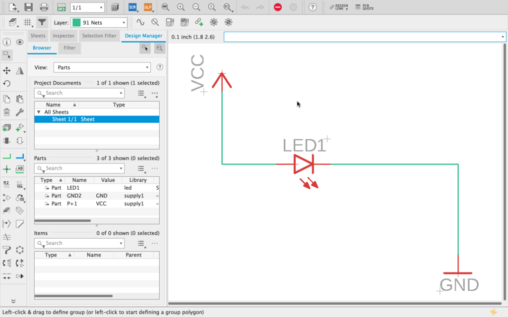
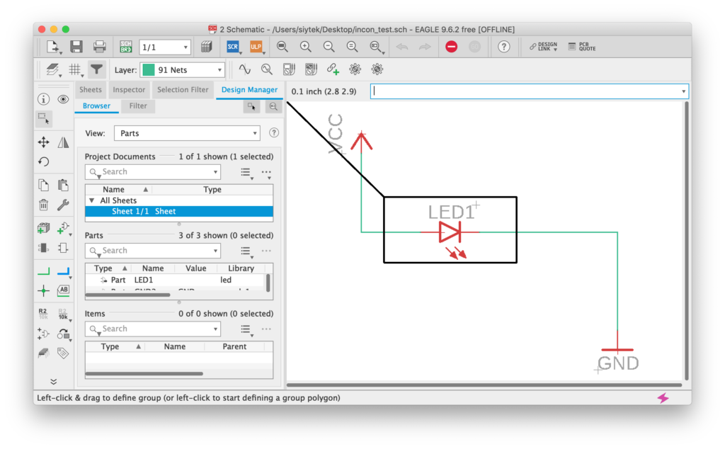
Let’s take a look at an example using the following simple schematic.
If we create a board file from this schematic, we would expect to begin with the LED1 component ready to place on the board, something like the following.
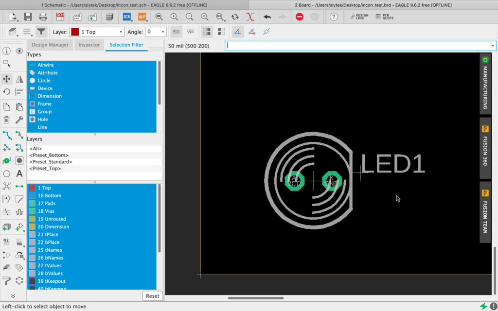
Now under normal circumstances, if you try to delete the LED from the board using either the delete tool from the left-hand menu, or by right-clicking the component origin, you will not be able to delete it.
This is because both the .sch and .brd files are open and EAGLE will not let you delete something from the board that is featured in the schematic.
You must remove the LED from the schematic in order to also remove it from the board and therefore both the board and schematic remain consistent.
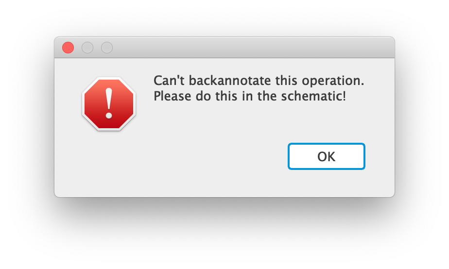
However there is a quirk in EAGLE that allows us to close the .sch file and make edits to the board such as being able to delete components.
Closing the .sch will cause EAGLE to produce a huge warning message, stating that the F/B annotation has been severed.
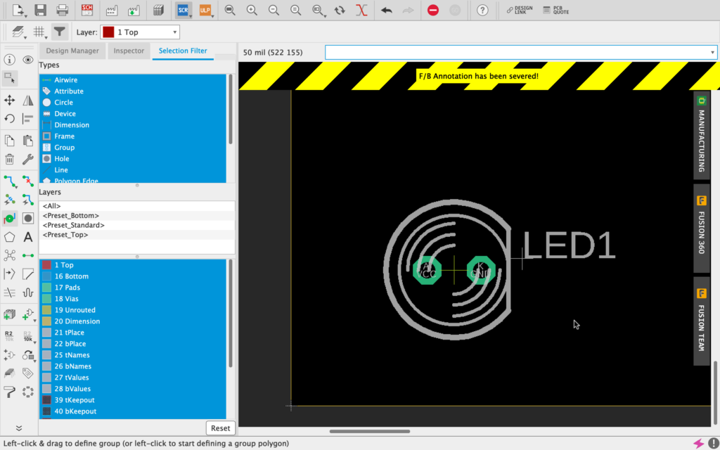
During this state it is now possible to use the delete tool to remove the LED from the design. In doing so it will create an inconsistency between the schematic and board.
This is because the schematic will contain a component named LED1, whilst the board will not contain it.
If we save the board now we will create the dreaded inconsistency error. Reopening the board will cause EAGLE to report the error.
How To Fix Board And Schematic Are Not Consistent With Error Checking (ERC)
Now that we have a basic error demonstrating a consistency problem, we can take a look at how to fix it.
Running the Electrical Rule Check in either the board or schematic editor will show us a list of consistency errors within the board schematic combination.
In the case of our example above it is possible to see the missing part causing the inconsistency error, which we deleted from the board and not the schematic.
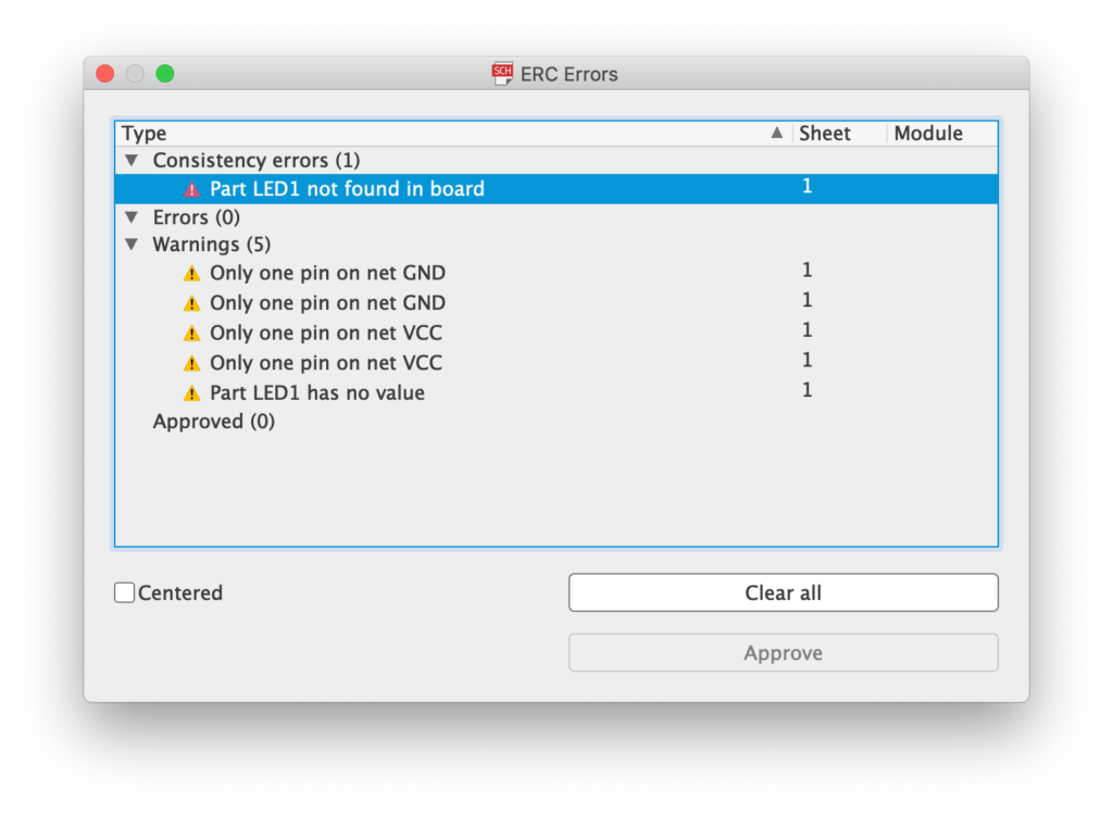
Clicking the error in the ERC window will show us the part in question within the schematic.
Of course this is not so necessary in such a simple schematic, however this can be very valuable when working with complex schematics containing many parts.
In order to fix the inconsistency we should replace the missing component in the board. First we can take a look at the details of the LED by right-clicking it and choosing properties.
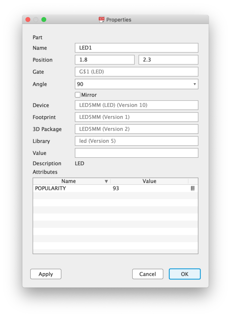
From this information we can see that it is a device called LED5MM within the library led.
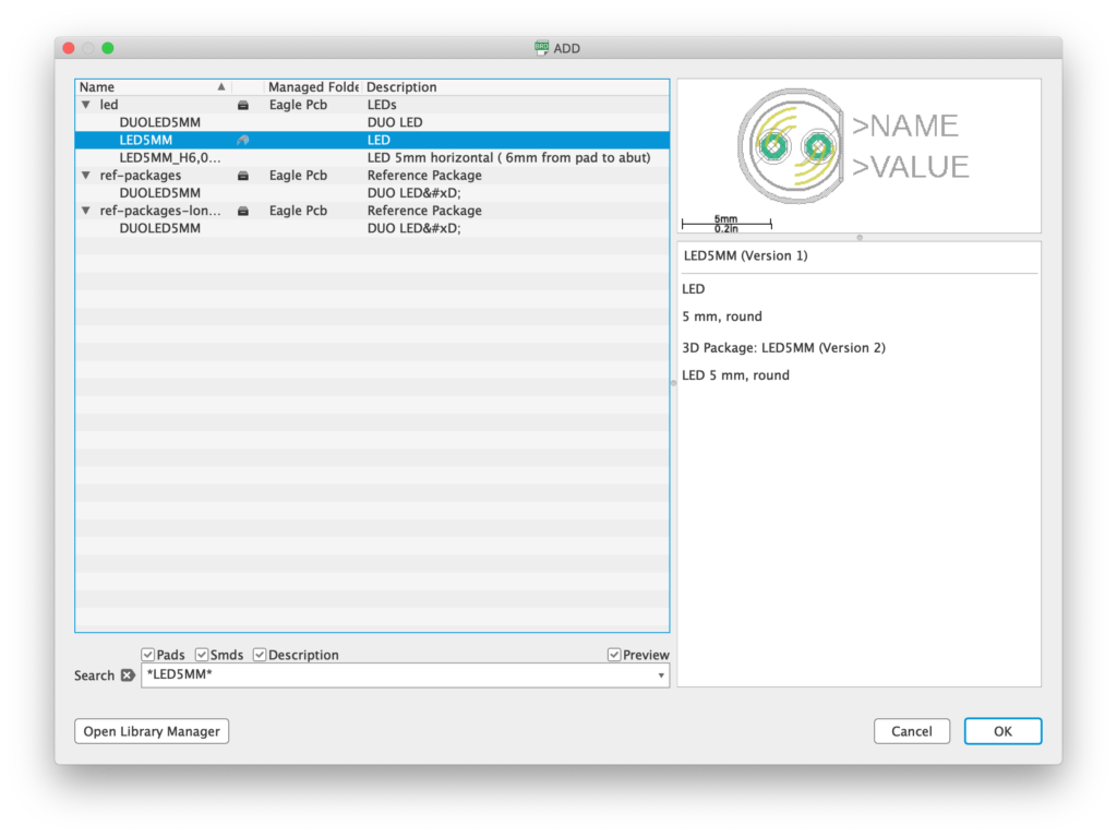
Now within the board editor we can choose add part from the left-hand toolbar and locate the part in order to add it back to the board.
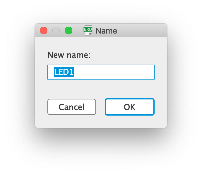
Once the LED has been added back to the board, we can right-click it and choose name in order to rename it to LED1 so as to match the name given in the schematic.
Now we can save both the board and schematic and run the ERC again. You will notice the consistency errors have changed to three new errors!
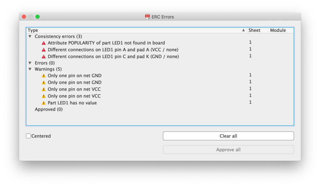
The first problem is a result of parameters from the schematic not being present within the board.
When a new board is created or components are placed in the schematic whilst the board is open, parameters are copied from schematic to board.
Adding missing components manually fails to also copy the required parameters. However thankfully there is a ULP program that we can use to correct this problem:
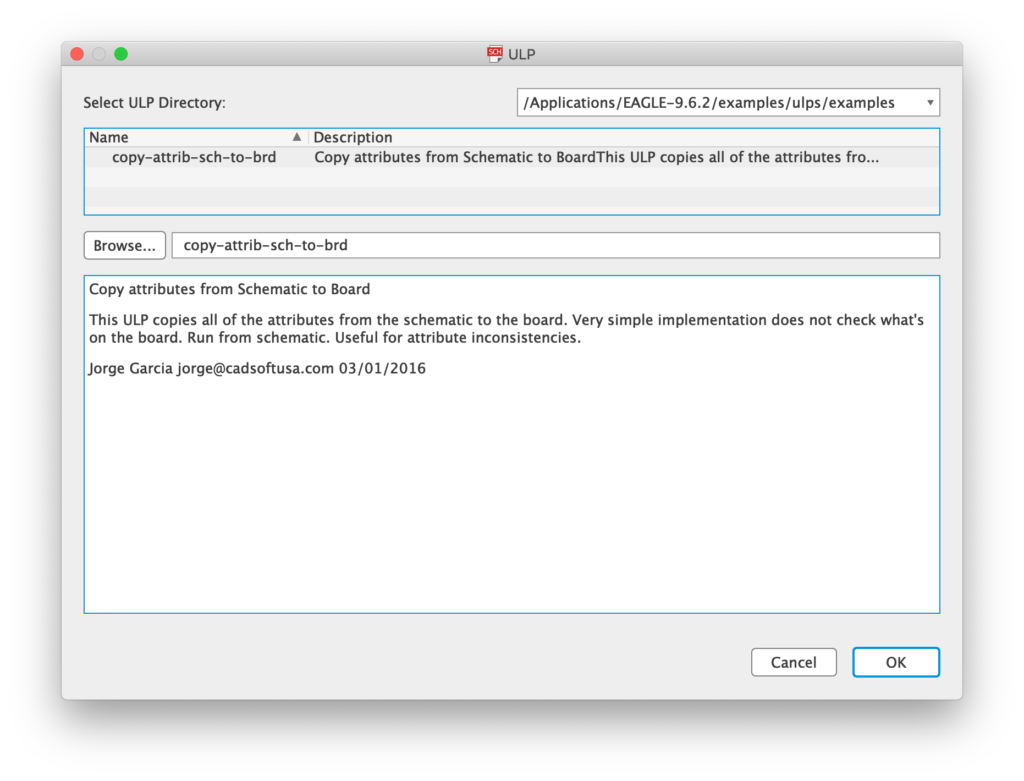
copy-attrib-sch-to-brd.ulp
This ULP program us a basic tool for copying the parameters across from the schematic to the board. It can be used to fix the missing attribute error within the ERC.
In order to run the ULP, from the schematic window, click File > Run ULP…
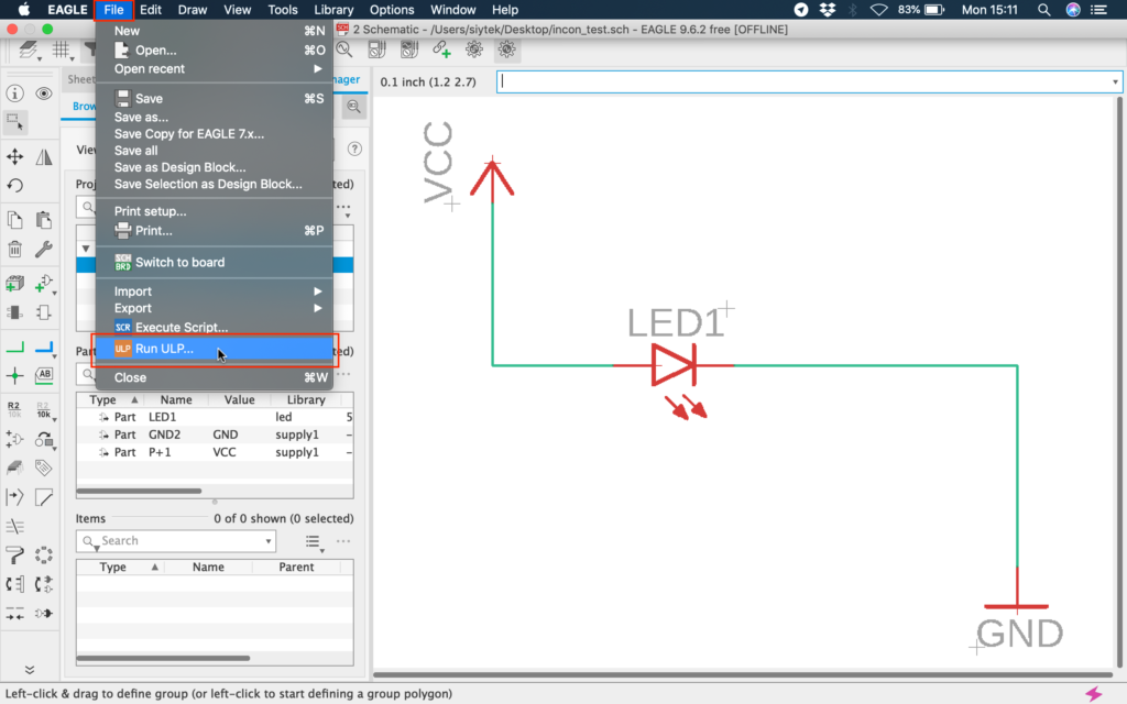
This will open the ULP dialog box, where we can locate the ULP. Enter the name of the ULP into the search box or you can locate it manually.
Click ok to run the ULP, you may receive a warning about board schematic inconsistency, just click ok to continue.
After the ULP has completed, run the ERC again from the schematic window and the first of the three inconsistency errors should be fixed.
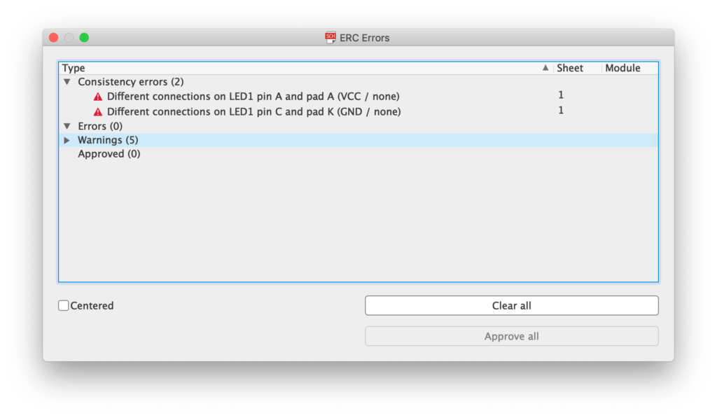
The remaining two errors are informing us that the A and K pins of the LED within the schematic are connected to VCC and GND, but within the board they are connected to nothing (none).
We can ‘patch’ this problem by deleting the nets within the schematic, so that the A and K pins of LED1 are also connected to none in order to match the board.

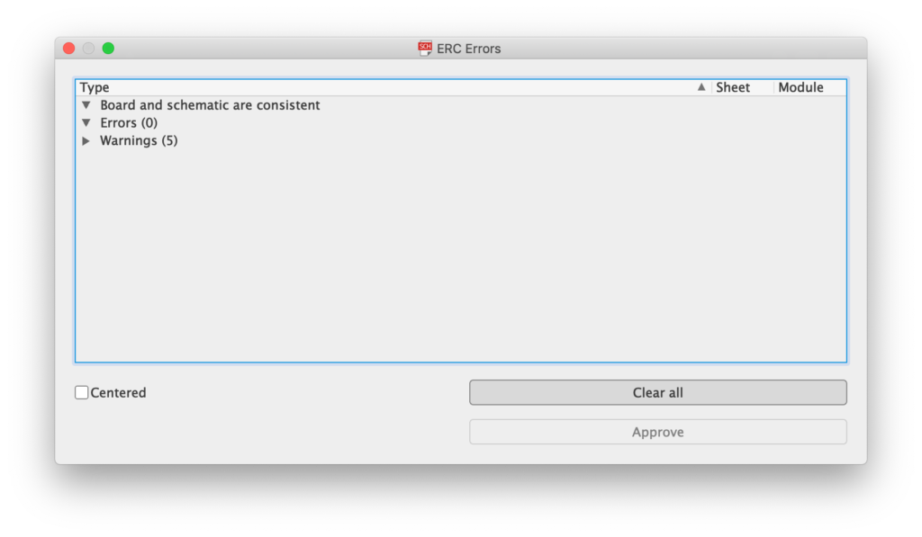
Simply delete the nets and save the schematic. Run the ERC again and the inconsistency errors will have disappeared.
How To Avoid Consistency Errors in EAGLE
Schematic and board designs within the EAGLE environment are kept in separate files, both using an XML format. During board design, the schematic and board are linked in order to keep consistency between the designs.
Problems with consistency occur when there is a discrepancy between the schematic and board design. Therefore, the single best way to avoid consistency errors is to ensure that both the schematic and board are edited simultaneously.
Problems can also occur if there are problems reading and writing to the schematic and board files. For example if the project files are stored in a network location or Dropbox/cloud type location, it is possible that there can be delays or failures to write the files correctly. These can certainly lead to consistency errors.
In order to avoid such problems when dealing with projects that need to be stored on a network drive, it is best to edit the files locally and then upload the changes after EAGLE has been closed.
Conclusion
It can be frustrating when something causes inconsistencies between board and schematic in EAGLE, however it is quite possible to systematically solve the errors.
If inconsistencies do occur then there are some steps that can be taken to correct the problem. However best practice is to avoid consistency errors in the first place by ensuring the project files are always opened simultaneously, and files are stored on a local drive whilst being edited.
Hopefully this guide will help you solve your inconsistency errors and avoid such errors in the future, good luck and happy designing!
If you like saving money, why not check out this article, which explains how to make a PCB more economically.
Thanks so much for visiting my site! If this article helped you achieve your goal and you want to say thanks, you can now support my work by buying me a coffee. I promise I won't spend it on beer instead... 😏