
Looking for the fastest and easiest way to go from zero to a completed PCB using Autodesk EAGLE? Maybe you are completely new to EAGLE, or perhaps just a little confused at its somewhat unorthodox user interface.
Well look no further! Here we will cover all of the EAGLE basics in a series of carefully crafted posts, which will walk you through the process from the first mouse click to the finished board.
Just in case you have stumbled upon this blog post in search of how to turn your electronic design ideas into a living, breathing and (hopefully!) functioning PCB, this post is also just for you.
Autodesk EAGLE is the most popular choice for hobbyists, makers, inventors and general electronics enthusiasts. It has a feature rich set of tools that give you everything you need to design a PCB and best of all, Autodesk have a lite version of the software that is absolutely free!
In subsequent posts we will cover all of the necessary steps required to complete your first PCB. In this first post in the series we will start with the first thing required in order to bring your idea to life.
Contents
- Creating A Schematic
- Adding Parts
- Copying Parts
- Adding Part Variants
- Adding a Supply
- Creating Nets
- Moving and Groups
- Adding Part Values
- Electrical Rule Check
- What’s Next…?
Creating A Schematic
The workflow in EAGLE is quite straightforward when you get used to it. We begin by creating a schematic diagram of the circuit that we wish to design a PCB for.
The schematic diagram contains all of the components that we wish to feature in our board design and details how they should be connected.
Each component is stored within a component library. There are many component libraries that come with EAGLE, so all of the common components have already been created for us. However it is possible to create new libraries and components, more on that later.
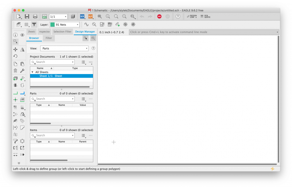
When you first open EAGLE, you will be presented with the following window.

On the left-hand side we are able to select from existing files within the EAGLE ecosphere. However as we wish to create a new schematic, lets click File > New > Schematic in order to open a blank schematic.
Adding Parts
Now at a glance it can look a little daunting! However as I mentioned earlier, EAGLE is feature rich and has many advanced editing tools. We can still produce a pretty sophisticated PCB using only the more basic tools shown here.
Let’s start by adding our first component to the schematic, by clicking the add part tool.
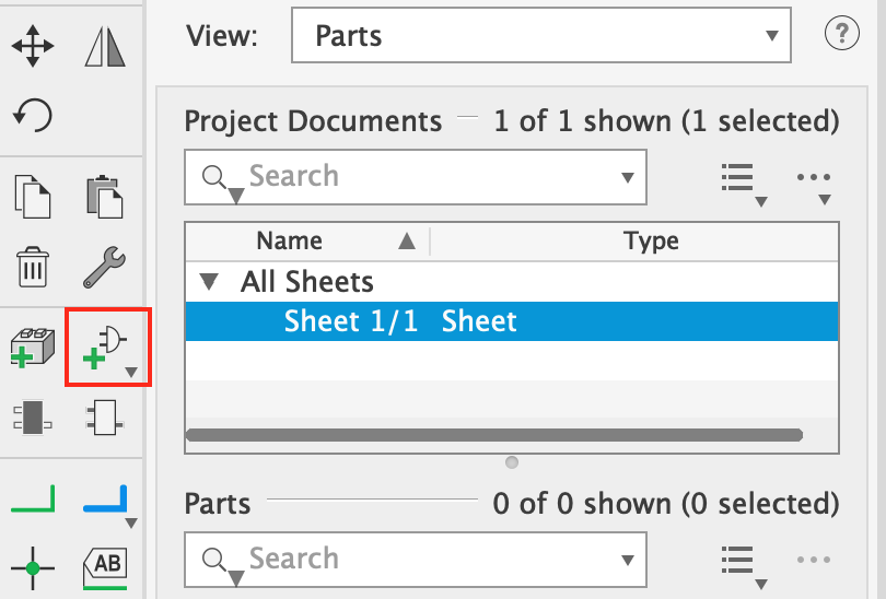
This button will open the add part window, which lists all of the currently installed libraries down the left-hand side. These libraries can be expanded by clicking the little triangle in order to display the components found within the library.
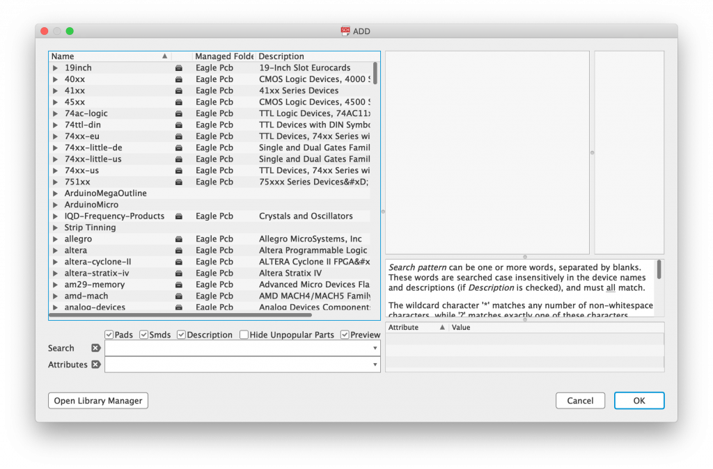
At the bottom of the window there is a search box. Here we can search for a particular component. It is worth noting a quirk with EAGLE, that is we should use * wildcards in the place of spaces.
Let’s find ourselves a 3mm LED using the search string LED*3mm.
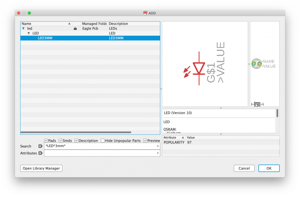
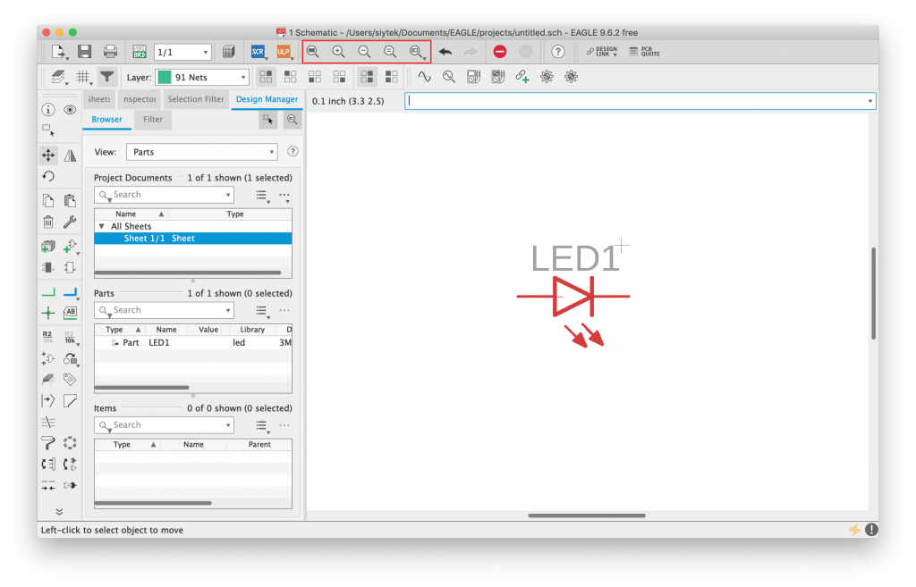
In order to place the component, we can simply click OK. This will close the Add Part window and allow us to place the component in a desired location.
It is worth noting that whilst grabbing hold of a component and moving it around the screen, it is possible to rotate it by right-clicking. Rotate the component and place it in the middle of the screen.
You can use the zoom tools at the top of the screen, or the scroll wheel / trackpad pinch to zoom into the component more.
Copying Parts
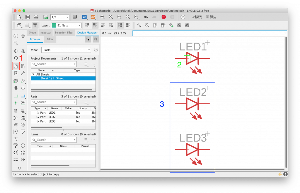
Next we can make a couple of copies of this LED. First click the copy tool on the left-hand pane (1), then click the part origin (2) and lastly place two copies of the LED beneath (3).
Adding Part Variants
Next we can add some current limiting resistors for the LEDs. Using the add part tool the same like before, we can search for resistors.
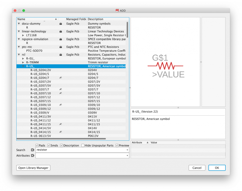
The two libraries containing the standard resistor components are R-US and R-EU. They contain symbols for US and European schematics respectively, feel free to use whichever you prefer.
In this example we will stick with US symbols and therefore we will use the R-US library. From the top of the list you will see a variety of through-hole resistors, R-US_0207 being the common 1/4 watt variety.
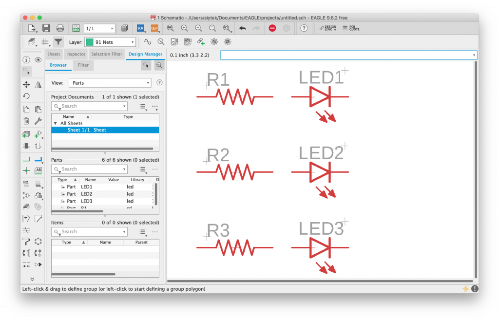
Let’s scroll down and add the R-US_R0805, which gives us a standard 0805 surface mount resistor, fairly easy to solder. Click OK and place 3 resistors behind each LED.
Adding a Supply
In this simple design, we will create a common ground for the LED cathodes. Using the add part tool, search for GND and add a grounding point to the right-hand side of the LEDs. In this example I chose the symbol from the supply1 library.
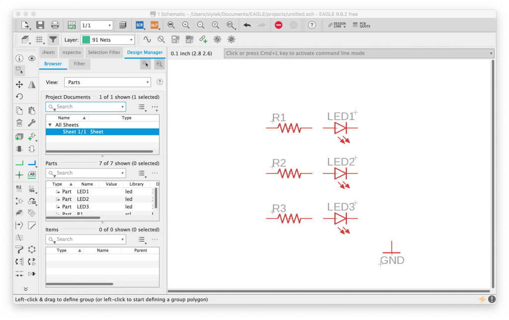
Creating Nets
Now that we have the basic components placed, we can connect them together. Each connection made in the design is known as a net and each is given its own unique name.
In the case of power supply or ground objects, the net will be named after the object. For example, all components connected to GND will be given the default net name GND.
Interconnecting nets will be given the default name N$n, where n equals an incremental number. However you can give these nets a different name if you prefer.
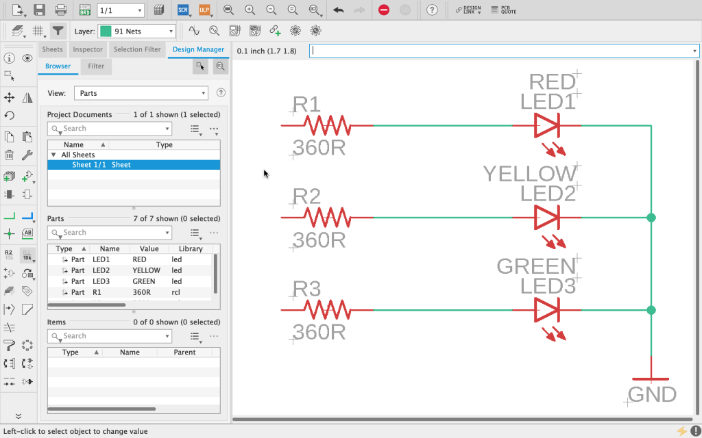
Let’s go ahead and connect each resistor to each LED, and connect all of the cathodes to ground as shown in the following image.
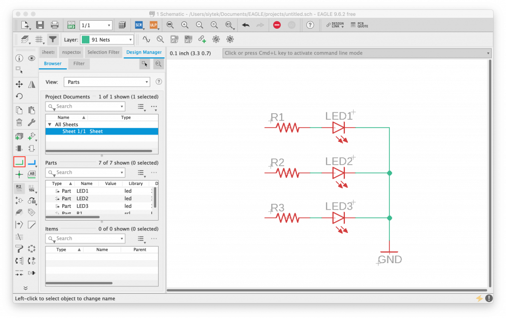
Moving and Groups
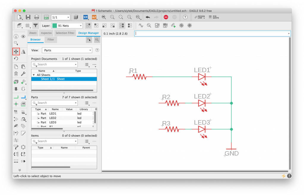
Now that we have placed the resistors, we can move them a little further from the LEDs. First we will move R1 by left-clicking it with the move tool and then left-clicking again to place it in a new location.
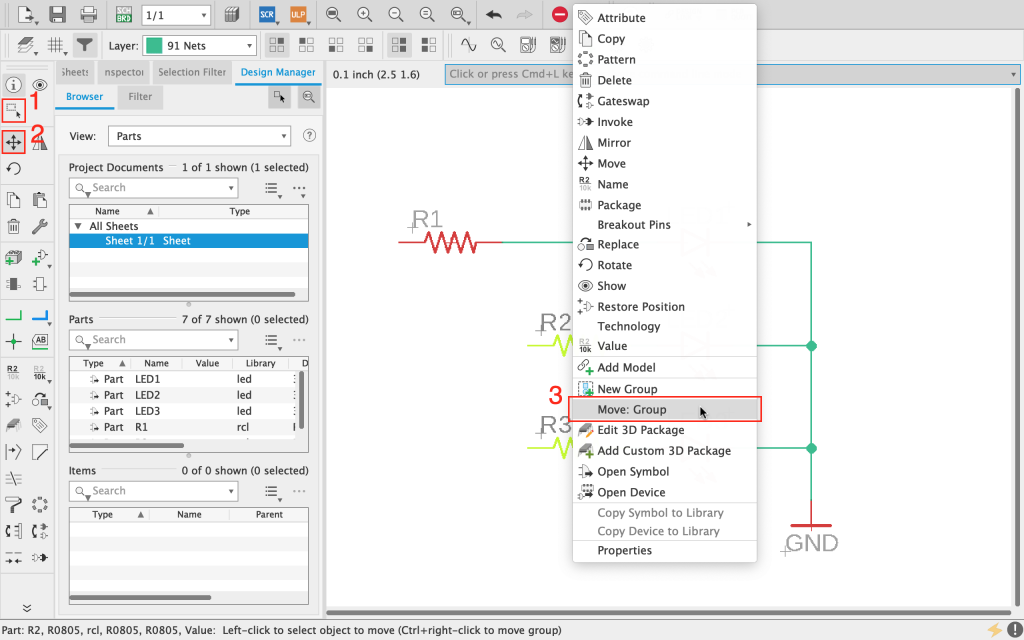
First use the select tool (1) to drag a box around R2 and R3. Once they are highlighted, choose the move tool (2) and right-click on the origin (the small + in the middle of the component).
Then click move: group (3) and you will be able to place the selected components at the new desired location.
Adding Part Values
At this stage we can add some values to the parts that we have created. Right-click on each of the resistors and choose value from the drop down menu.
Here we have added a value of 150 ohms to each of the LED current limiting resistors. The value was calculated using this LED calculator and will allow us to power our LEDs from a 9V battery.
We can also give a value to each of the LEDs. In this case we can indicate the desired colour. At a later stage we can choose whether or not to print the values in silkscreen on the PCB to make it easier to assemble.
Electrical Rule Check
You will notice that we do not yet have a power source in our circuit and the resistors are currently not connected at one side.
This was intentional as an important step in designing a schematic is knowing how to run the design checks. This can save you the heartache of receiving your brand new shiney PCBs from the fabricator, only to realise that there is a design error! (Yes, it has happened to me before and it is the definition of disappointment!)
It is of course very obvious to see the error here with the resistors that are connected. However in a more complex schematic this tool can prove to be a lifesaver when discovering errors that are not so obvious.
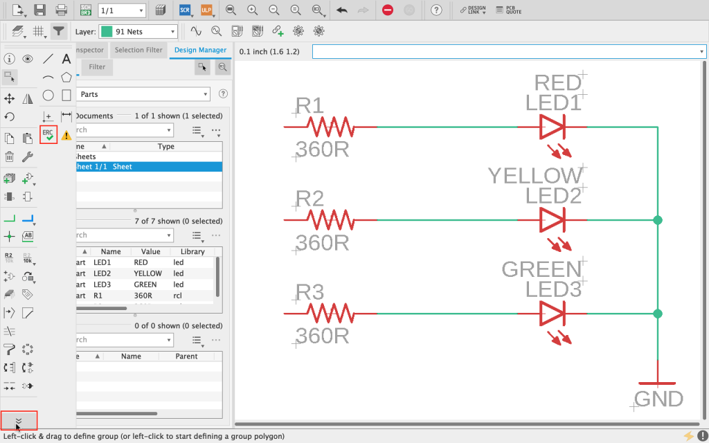
In order to run the electrical rule check, expand the toolbar using the three-arrow button at the bottom left of the toolbar and then click the ERC tool.
When you click the tool a dialog box will open showing all of the design errors found in the schematic. In this case we would expect to see a report of the three resistors that are disconnected.
Clicking on each item in the report will draw a line from the corner of the screen and surround the area in question with a black box, so you know where the error is located.
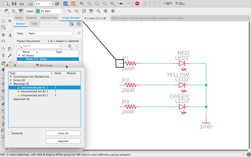
The ERC will display different categories of warning. In this case the unconnected pin is listed as a warning rather than a more severe error state.
In both cases you have the choice to fix the error or mark is as approved. If for example you intentionally did not want to connect a pin, you could mark the warning as approved by clicking the approve button and it would be moved into the approved section.
This allows you to ignore things in the schematic that are being detected, but that are intentional or not of concern. However in this case we will rectify the error and run the ERC again to see if the warnings have been cleared.
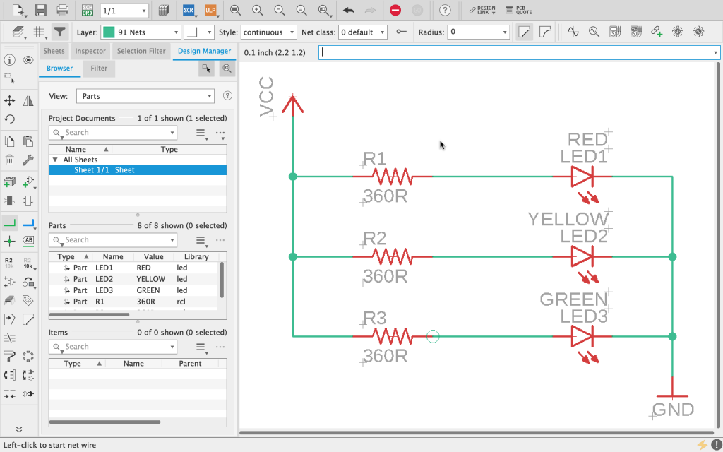
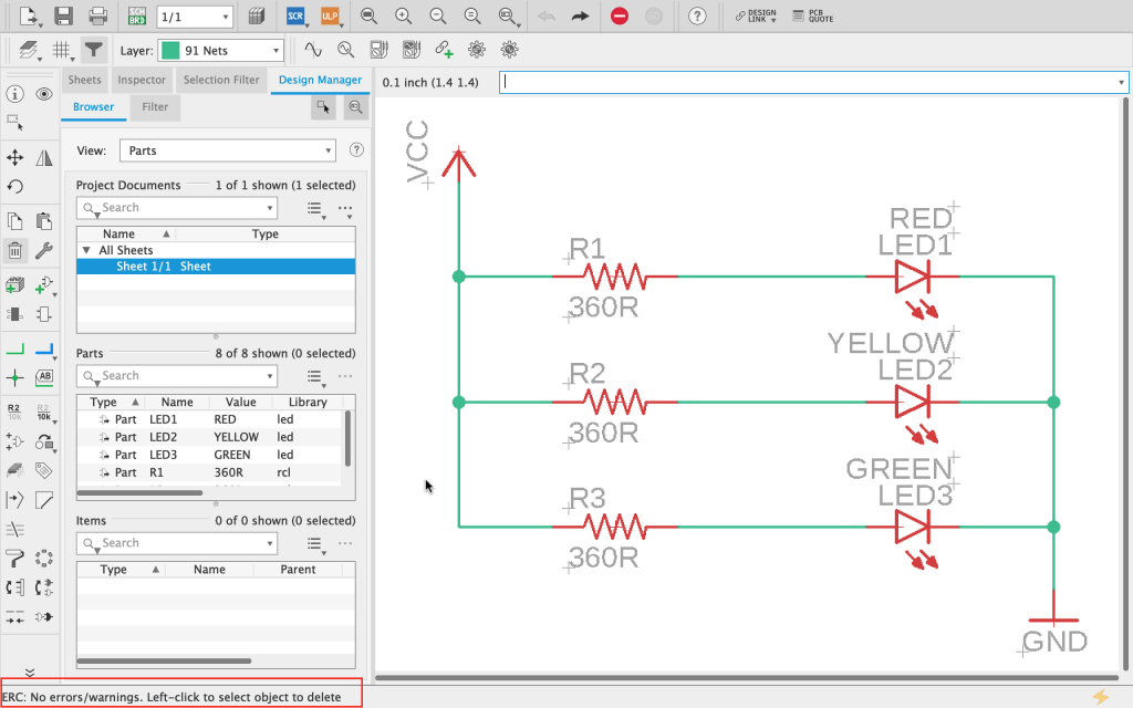
First close the ERC dialog box and then click on the add part tool in the toolbar. Search for “vcc” and add VCC from the supply1 library. Then connect VCC to the unconnected resistors as shown in the following screenshot.
Now we can run the ERC again to see if this has corrected the errors. You will probably find yourself clicking the button over and over, wondering why the ERC dialog will not open, right? This is another little quirk of EAGLE.
As there are no errors and EAGLE has nothing to do, the dialog will not open. However you will see in the bottom left of the screen a report stating that no electrical errors have been found. Voila! Our schematic is good to go!
What’s Next…?
Congratulations on completing the first steps towards bringing your PCB design to life! So far we have covered enough basics to complete a schematic design in EAGLE.
In later tutorials we will cover some of the more advanced tools. These are useful for more complex designs and also for speeding up your workflow.
You will have probably seen that there are many different components in the EAGLE component libraries and also there are many sources that you can download custom libraries.
With that said you will inevitable run into a situation whereby you need to add a component to the library, therefore a key part of creating a schematic is knowing how to design a custom component.
In the next article we will cover the basics of the EAGLE library editor and how to take a component datasheet and turn it into a custom library component.
We will be adding a simple tactile switch to a brand new EAGLE library, and then adding it to our current schematic.
Check out the next tutorial in the series… How To Make A Custom Part And Library In Autodesk EAGLE
Thanks so much for visiting my site! If this article helped you achieve your goal and you want to say thanks, you can now support my work by buying me a coffee. I promise I won't spend it on beer instead... 😏