One of the key benefits to using microcontrollers is that they offer a series of input and output pins that can be used for a whole variety of different things.
Awesome! But what does that actually mean?
Input and output pins, or IO for short, can be configured to control external peripherals, communicate with other digital devices and read the state of connected buttons, switches and dials.
Microcontrollers allow you to build your own hardware device as if you were building Lego.
Personally I always found electronics exciting for this reason… it brings software development into the real world!
In order to use IO pins to bring our projects to life we need to program them to behave in a certain way, which is where MicroPython comes in.
MicroPython makes programming the functionality of these IO pins really easy!
Ready to start building awesome projects? Great! In this tutorial you will learn:
- How to load the library necessary for controlling IO pins.
- How to configure IO pins.
- How to read and write to IO pins.
- What external interrupts are and how to use them.
- What pulse width modulation is and how to use it.
Table of Contents
- Prerequisite
- How To Use GPIO Pins in MicroPython
- How To Use the Analog Pins in MicroPython
- How To Use PWM in MicroPython
- How To Use External Interrupts in MicroPython
- Whats Next?
Prerequisite
This tutorial assumes that you are already up and running with MicroPython.
This means that you should have a compatible board with the MicroPython firmware already installed. You should also have access to the REPL prompt.
If none of that makes any sense, don’t worry!
All you need to do is first visit the tutorial that explains how to setup MicroPython and use the REPL prompt to get up to speed.
I would also recommend using an ESP8266 compatible board such as the Wemos D1 Mini as this is what will be used in the tutorial, although any MicroPython compatible board should work just fine.
How To Use GPIO Pins in MicroPython
Microcontrollers such as the ESP8266 refer to their IO pins as GPIO, which is short for general purpose input output.
GPIO pins can be configured as either input or output pins. They sometimes feature an internal pull-up resistor that can be enabled in software.
The ESP8266 also has an analog pin that can be used to read analog voltages, within the limits of the chip specification.
How to Include the MicroPython Machine Module
In order to use the IO pins on our microcontroller we must first load the machine module. To demonstrate its usage we will import it directly using the REPL prompt.
At the REPL prompt, enter the following command to load the machine module:
import machine
It is also possible to import submodules from a module using import from:
from machine import Pin
How to Construct GPIO Pins with MicroPython
Once we have loaded the machine module, we can construct pins with the following command:
pin_name = machine.Pin(<pin number>, <direction>, <pull up>)
The pin_name can be anything you want to name the pin.
Pin number, direction and pull up should be replaced with appropriate values depending on how you want to configure the pin:
- pin number – represents the physical pin that you want to configure.
- direction – whether the pin is an input or output pin.
- pull up – whether or not the internal pull-up resistor is active.
For example, if we wanted to configure GPIO pin 0 as an input pin with the pull-up resistor activated, we would use the following:
mypin = machine.Pin(0, machine.Pin.IN, machine.Pin.PULL_UP)
Pin Number
The pin number is a numerical value that represents the physical pin that will be constructed. The number of pins available for configuration will depend on the microcontroller board that you are using.
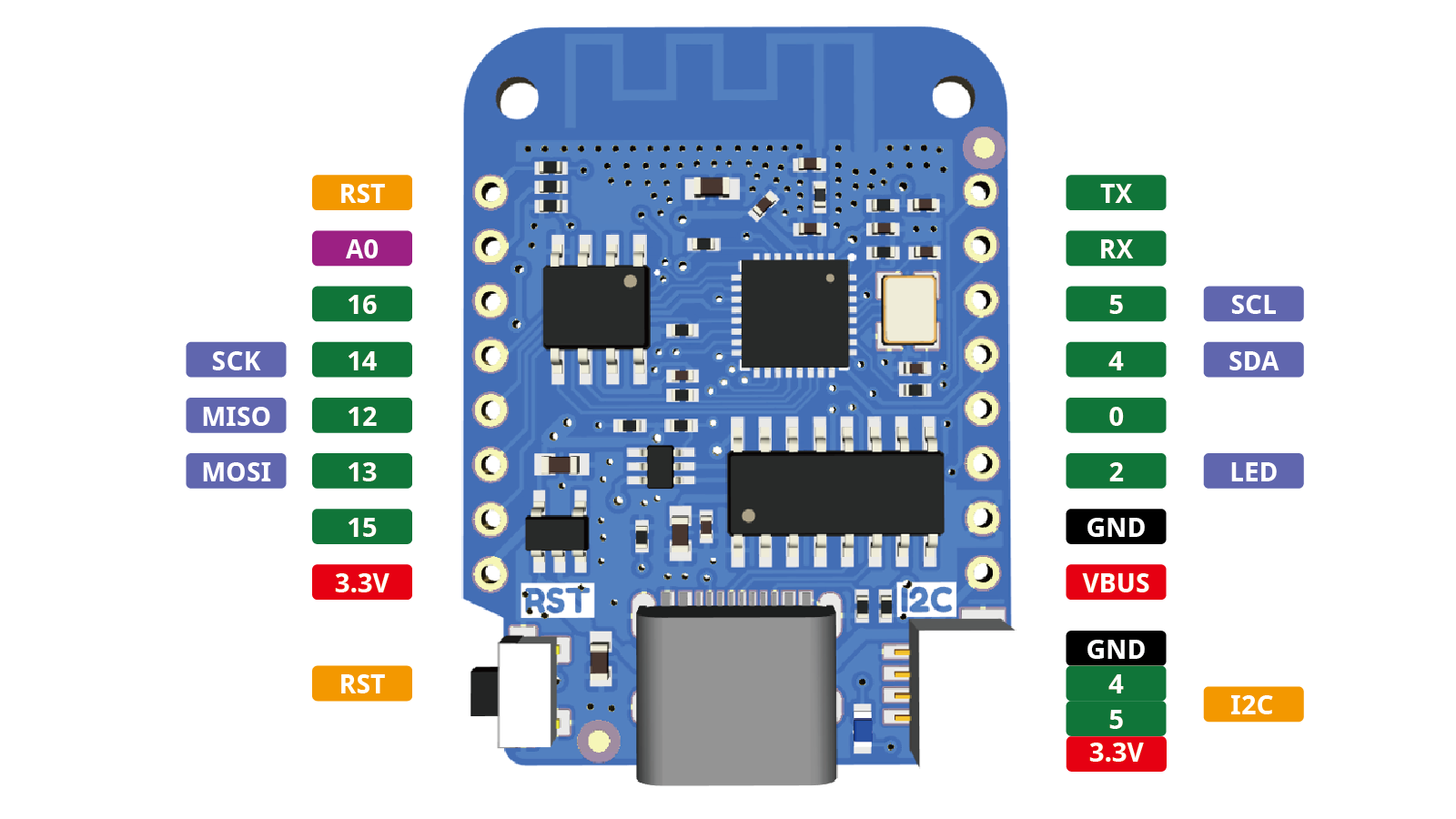
As this tutorial series is based on the ESP8266, more specifically the Wemos D1 Mini, we will look at the available pins for this board.
The following diagram shows the pinout for the Wemos D1 Mini:
Direction
The pin direction specifies whether or not the pin should be input or output:
- Input – when the pin is set to input mode, the microcontroller can read either a 1 or 0 value depending on whether or not a HIGH or LOW voltage is applied respectively:
- For a LOW reading the voltage must be under 0.825V
- For a HIGH reading the voltage must be over 2.475V
- Output – when the pin is set to output mode, the microcontroller can write either a HIGH or LOW value to the pin:
- A LOW output pulls the pin to GND
- A HIGH input pulls the pin to VCC, 3.3V.
In order to set the direction, the parameter machine.Pin.IN or machine.Pin.OUT should be specified as the parameter after the pin number.
Internal Pull-up Resistors
It is common for a microcontroller to feature pull-up resistors on some or all of their GPIO pins. This can be very useful for simplifying design and reducing component count.
So what on earth is a pull-up resistor?
In electronic logic circuits, a pull-up resistor (PU) or pull-down resistor (PD) is a resistor used to ensure a known state for a signal.
– Wikipedia
It is beyond the scope of this article to go into too much detail, however there is an excellent explanation here if you need further clarification.
When using the GPIO for input we can activate the pull-up resistor by specifying the third attribute; machine.Pin.PULL_UP
You can disable the pull-up resistor by setting the attribute to none, which is also the default value if nothing is specified.
GPIO Pin Example in MicroPython
Now that you have a good understanding of how to use GPIO pins in MicroPython, let’s take a look at an example.
Most microcontroller boards have a basic LED connected to one of the GPIO pins.
If we take a look at the pinout diagram for our Wemos D1 Mini, we can see that GPIO pin 2 has the LED connected (as indicated by the label ‘LED’).
Let’s take a look at how to control this pin at the REPL prompt.
First go ahead and load the machine module:
import machine
Next we need to construct the pin. We will set GPIO2 (the LED pin) to an output pin:
LEDpin = machine.Pin(0, machine.Pin.OUT)
Now we can control the LED by setting the GPIO either HIGH or LOW. This can be done with two different commands:
LEDpin.value(0)
LEDpin.value(1)
You can also use the following command:
LEDpin.off()
LEDpin.on()
Remember that LEDpin should be changed to whatever name you have chosen for your pin.
It is also worth noting that depending on the board that you are using, the LED state might be reversed.
For example the LED on Wemos D1 Mini boards is connected to 3.3V and not GND. To complete the circuit the GPIO pin must be in a LOW state for the LED to switch on.
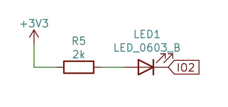
This means that the state is reversed, for example LEDpin.off() will turn the LED on and LEDpin.on() will turn the LED off.
How To Use the Analog Pins in MicroPython
The GPIO pins that we have looked at so far are digital pins. This means they can either be in a HIGH or LOW state.
Microcontrollers usually also feature one or more analog to digital converter (ADC) inputs, which can convert an incoming analog signal into a digital value.
What?! But isn’t analog some antiquated technology of yesteryear?! No not exactly.
In the digital realms a signal can either be in a HIGH or LOW state. This is great if we want to:
- Read the value of a switch, which can either be OFF or ON.
- Switch an LED into an ON or OFF state.
- Communicate with another device using a digital signal.
However what if we want to use a good old fashioned knob on our project?

A knob can be in a LOW state when turned all the way down, a HIGH state when turned all the way up, but it can also have a value anywhere in the middle.
This is what analog fundamentally means in terms of electronics; a variable signal.
In order to represent the position of a knob we can use a variable voltage. When the knob is turned fully to one direction the voltage is 0V.
As the knob is turned towards the other direction, the voltage increases in proportion to the position of the knob, until it reaches the highest voltage, usually equal to the supply voltage VCC.
This is where the analog input comes in. We can use the analog input on our microcontroller to read this voltage and convert it into a value that we can use in our program.
The Wemos D1 Mini features an ESP8266, which has a single analog input pin. For more information you can check out my article specifically about the ESP8266 analog input.
How to Convert Analog to Digital using MicroPython
To complete this part of the tutorial it is not mandatory to connect a signal to the analog pin, although I would advise that you do so in order to see a real world example.
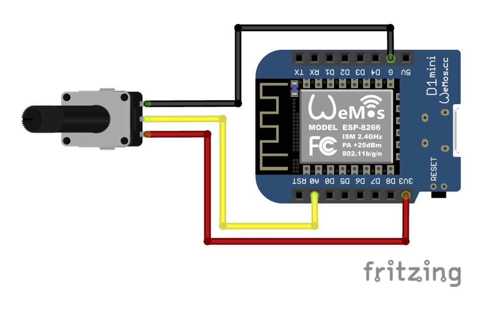
The easiest way to provide a variable voltage to the analog pin is by connecting a knob (potentiometer is the technical name, or pot for short) to the supply voltage and analog pin.
The following diagram shows how to do this with an Wemos D1 Mini / ESP8266:
In order to read the value of the pot, we first must load the machine module at the REPL prompt:
import machine
The Wemos D1 Mini has only one onboard analog input (Shown as A0 on the pinout diagram) as the ESP8266 microcontroller is limited to just one analog input.
Other microcontrollers will have more than one analog input available, so A1, A2, A3 and more can be available.
Once we have loaded the machine module, we can construct the analog pin:
ADCPin = machine.ADC(0)
Lastly we can read the value of the pin using the following command:
adc.read()
This will return a decimal value between 0 and 1023 that is proportional to the input voltage, where 0V will give 0 and VCC (equal to the 3.3V supply voltage) will give 1023.
The reason the maximum value is 1023 is because the ESP8266 has a 10-bit ADC and 1023 is the maximum number that can be represented by 10 bits.
More bits give exponentially higher upper values and finer resolution. Analog to digital converters with a higher number of bits can sense smaller changes in voltage.
How To Use PWM in MicroPython
In the previous section we discussed how to use the analog input, but what about analog output?
Well… there isn’t one!
What we do have is something called PWM, or pulse width modulation, which provides a variable signal output.
However unlike the analog input which receives a variable input voltage, PWM does not vary the voltage.
A PWM signal switches from a HIGH state to a LOW state very quickly. The frequency can vary between microcontrollers but the ESP8266 switches at between 1Hz and 1kHz, which is 1000 times per second at the fastest possible rate.
It is the ratio of time between how long this signal is in a HIGH state versus how long it is in a LOW state that is the variable.
This is called the duty cycle and can be used for many cool things in electronics.
For example, if you switch an LED between a HIGH and LOW state at 1000 times per second, it is too fast for the eye to perceive. This is called persistence of vision.
If the LED is in a HIGH state for 50% of the time and a LOW state for 50% of the time, the LED will appear as if it is illuminated to 50% of its maximum brightness.
If the LED is in a HIGH state for 75% of the time and a LOW state for 25% of the time, the LED will appear as if it is illuminated to 75% of its maximum brightness.
Therefore you can see how a PWM output can be used to control the brightness of an LED.
For further reading about PWM you can check out my guide to PWM and LED dimming here.
Using PWM to Dim an LED in MicroPython
In order to test PWM in MicroPython we can use the onboard LED again. In the case of the Wemos D1 Mini the onboard LED is GPIO 2.
First we need to import the machine module:
import machine
Next we need to construct a digital pin:
LEDpin = machine.Pin(2)
Then we need to create a PWM object using the pin that we just created:
LEDpwm = machine.PWM(LEDpin)
Like with the ADC, the PWM operates with a 10-bit value between 0 and 1023. Here are some examples:
- 0 = 0% duty cycle, LED is switched off.
- 512 = 50% duty cycle, LED is 50% brightness.
- 767 = 75% duty cycle, LED is 75% brightness.
- 1023 = 100% duty cycle, LED is switched on.
Note that these values can be reversed depending on how the LED is wired. In the case of the Wemos D1 Mini the values are reversed.
Now we can control the brightness of the LED by changing the PWM duty cycle:
LEDpwm.duty(512)
It is also possible to change the PWM frequency:
LEDpwm.freq(500)
You can also check current PWM values by entering the PWM object or freq() and duty() functions without any arguments.
LEDpwm
freq()
duty()
Lastly, if you want to stop a pin functioning as a PWM pin, you can use the following:
LEDpwm.deinit()
Using PWM to Control a Servo in MicroPython
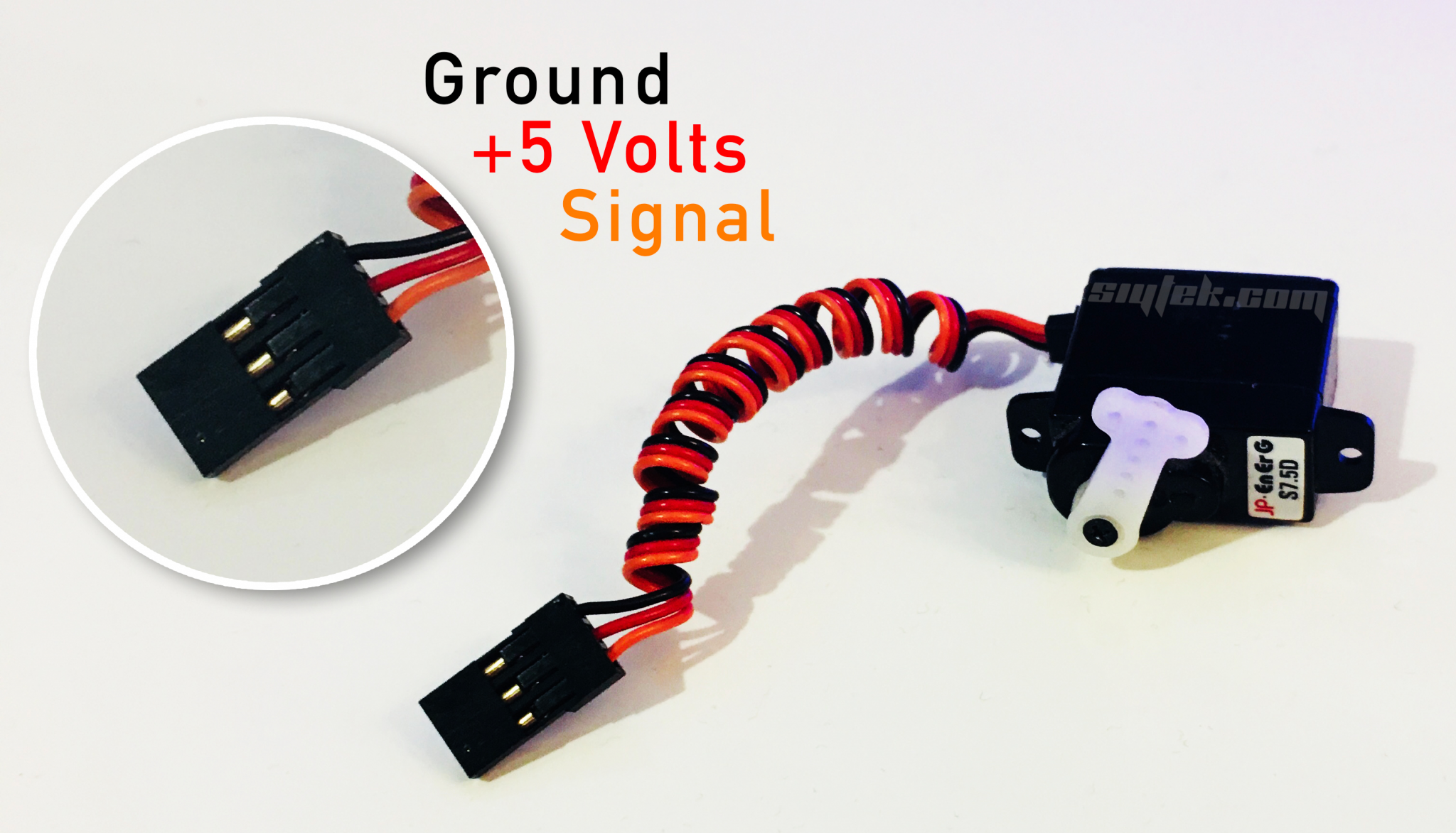
You may be familiar with the ubiquitous hobby servo, a staple part of the makers toolkit.
Standard analog servos are actually controlled by a PWM signal, so it is possible to use PWM in MicroPython to control their position.
In order to use a servo with MicroPython you will need to connect it to a power source, usually 5V (note that this is higher than the 3.3V used to supply an ESP chip).
Therefore your circuit will likely require a seperate power supply for the servo:
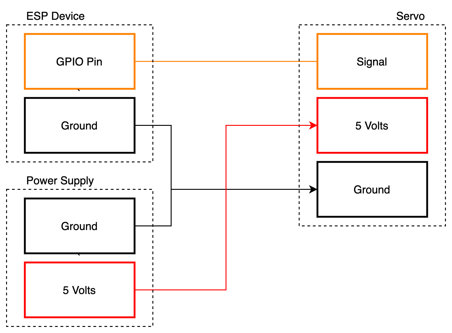
Assuming that you have the wiring in place, the next thing to do is configure PWM in MicroPython. First we need to import the machine module:
import machine
Then you need to construct a pin and PWM object for the servo, choosing the GPIO pin that the servo signal is connected to.
We will also set the frequency to 50Hz, which is required for a hobby servo. Note that you can do this in the PWM constructor:
servo = machine.PWM(machine.Pin(12), freq=50)
Now we can control the servo position by adjusting the duty cycle:
servo.duty(40) # minimum servo position
servo.duty(77) # middle servo position
servo.duty(115) # maximum servo position
How To Use External Interrupts in MicroPython
An interrupt with regards to a microcontroller is usually a temporary event that occurs due to an external stimulus, which interrupts the main program.
A particular interrupt can be setup to trigger a particular function as a matter of priority, before the microcontroller returns to the place within the main code where it was first interrupted.
A very basic example of an interrupt could be a simple push switch that was connected to a GPIO pin of a microcontroller that is continually displaying sensor values on an LCD display.
When the switch is pressed, it triggers an interrupt that halts the current process of reading sensor and diverts to a section of the program that displays a user menu on the LCD display.
Once the user exits this menu, the interrupt completes and the program returns to the same place where it was as the interrupt occurred.
Let’s take a look at an example.
First we need to write a function that will be called when the interrupt is triggered:
def interrupt(p_state):
    print('pin change', p_state)
Next we need to construct a pin that we would like to use for our interrupt. Note that this pin should be an input.
We will also import Pin from the machine module.
from machine import Pin
int_pin = Pin(0, Pin.IN)
Now we can configure this pin as an interrupt.
int_pin.irq(trigger=Pin.IRQ_FALLING, handler=interrupt)
The first argument specifies whether action should occur on the RISING or FALLING edge of the pin state change.
The second argument specifies the target function that should occur on the interrupt.
Note that it is possible to specify the event on both the rising and falling edge using the pipe symbol:
int_pin.irq(trigger=Pin.IRQ_RISING | Pin.IRQ_FALLING, handler=interrupt)
In order to test this code you can connect the pin that you specified for the interrupt to either GND or VCC. The change of state will be printed in the terminal.
Whats Next?
In this tutorial we have covered the main types of IO pins found on the ESP8266 and how to use them with MicroPython. We have covered digital, analog and even PWM!
Congratulations for getting this far!
In the next tutorial we will be taking a look at networking in more detail, including how to make that coveted ESP8266 web server!
Thanks so much for visiting my site! If this article helped you achieve your goal and you want to say thanks, you can now support my work by buying me a coffee. I promise I won't spend it on beer instead... 😏