Why spends hundreds on a smart thermostat when Home Assistant has the power to control all of the necessary hardware and it’s absolutely free?!
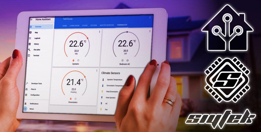
I agree that the Google Nest looks beautiful but if you really want to wow your friends, why not mount a tablet to the wall and make an awesome looking dashboard!
You’ll have something more unique and unlike an (expensive) smart thermostat, you will be able to control your whole house from the dashboard!
This tutorial aims to cover all of the details for designing your own Home Assistant based HVAC control system, including multiple zones and air conditioning. If you are looking for a quick and simple solution, you may want to check out my quick and easy guide to a heat-only thermostat instead.
Table of Contents
- Prerequisite
- Disclaimer
- Understanding HVAC
- Example Configurations
- Diagrams
- Choose a configuration
- System modification
- Hardware Entities
- Wiring
- Configuring Home Assistant
- Conclusion
Prerequisite
For this tutorial we will assume that you have Home Assistant up and running already. Knowledge of configuration.yaml and the YAML language is also required as this tutorial is a little more advanced.
If you are new to Home Assistant and don’t have any experience with YAML, I would recommend checking out one of my other tutorials first.
- Beginners guide to scripts and automation.
- How to automatically dim the lights using home assistant when watching a movie
- How to simulate a sunrise with Home Assistant
- How to control all of your smart devices with your existing dumb light switch
Temperature sensor
You will need at least one temperature sensor to report the temperature back to Home Assistant. I would recommend locating it somewhere near to the original thermostat, particularly if you are using a boiler type system.
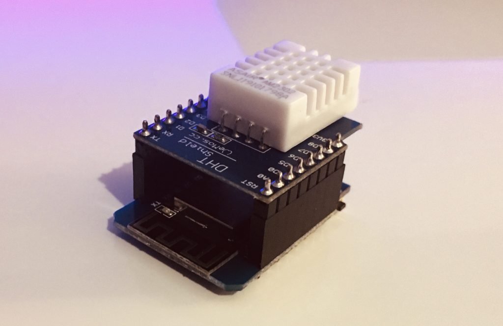
If you don’t have a temperature sensor in mind then would recommend building your own temperature sensor using a Wemos D1 Mini and DHT22. I have a detailed guide that makes this very easy and you can build one for around the price of a beer!
It is very easy to make and can be powered from a USB connection. I currently power mine from an old USB charger but I have future plans to install it inside a DIY smart lamp.
If you have more than one thermostat in your house then you will need a minimum of one temperature sensor for each zone, ideally located near each of the original thermostats or at least in the same room. In my case I have two zones, upstairs and downstairs. Therefore I will install two temperature sensors.
Relay switch
You will also need a smart switch with at least one relay in order to control your boiler/furnace. I would recommend one of the ubiquitous Sonoff switches.
If you have a furnace and air ducting then you will need an additional relay switch to control the fan. If you have a boiler and radiator system then the pump will likely be integral with the boiler and no additional relay switch is needed.
If you have either an integrated AC unit or would like to include a standalone AC unit, you will need another relay switch to control it. Alternatively if you have a standalone AC unit with a remote, you can use an IR blaster.
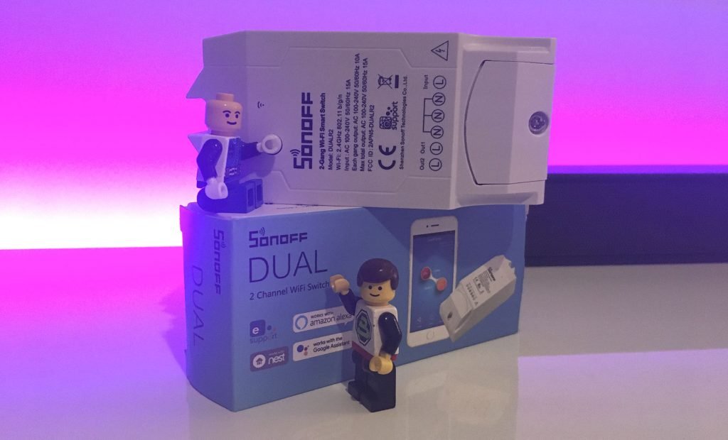
As I have a dual zone heating system I have two thermostats, one for upstairs and one for downstairs. I will be using the Sonoff Dual R2 as it has two relay switches and I can use one for each zone.
If you only have a single zone with one thermostat, you will only need a single relay switch, something like the Sonoff basic will do just fine. If you want to integrate your relays and temperature sensor into your existing thermostat wall box, you can use a 5V relay module connected to the Wemos D1 Mini that you use for your temperature sensor.
These are only suggestions and you can use any sensor or switch that you like, so long as it can be recognised and controlled with Home Assistant.
Disclaimer
Please do not attempt to make any modifications to your HVAC system unless you are absolutely certain you understand what you are doing. I am not a HVAC engineer and offer this information with absolutely no guarantee that it will work with your HVAC system.
There are many different configuration of HVAC system so you need to gain a full understanding of your own system and how it is configured. This information is purely for educational purpose only.
If in doubt, stop and seek expert assistance from a qualified HVAC engineer.
Understanding HVAC
As there are many different possible configurations we will take a look at things from a more generalised perspective.
One thing that remains the common is each system has a method of heating or cooling and is controlled by a thermostat, which measures the temperature in the room. We can break things down into two categories, single zone and multiple zone systems.
Single zone system
In a single zone system the HVAC components control the temperature within the home globally. The system consisting of a single thermostat that either heats or cools the home depending on the desired temperature vs the actual temperature.
In a heat only system either a boiler or furnace delivers heat to the entire home either with hot water or hot air respectively.
A full HVAC system also features the ability to cool the home by means of cold air. The chiller can either be integrated and share the ducting used by a hot air system or it can be a standalone AC unit.
Multi zone system
A multi zone system features the same configuration as the single zone system but with the addition of valves or dampers to direct the heat source to different locations. An common example would be independent zones for the upstairs and downstairs areas of a home.
In a system consisting of a boiler, valves are used in the pipework to stop or allow the flow of hot water to designated zones.
In a system consisting of a furnace either with or without an integrated AC unit, dampers are used in the air ducting to stop or allow the flow of hot or cold air to the designated zones.
Standalone AC
Some systems only have the ability to produce heat, which include all boiler systems and ventilation systems that do not have an integrated AC unit.
In this case it is possible to add a standalone AC unit to our Home Assistant thermostat control. A single or multiple units can be used either in a single zone system or grouped to match the zones of a multi zone system.
A huge benefit of using Home Assistant as your smart thermostat is that you can easily integrate a standard “dumb” AC unit using either a smart plug to switch the power or an IR blaster if the unit has a remote control. Something beyond the ability of a commercially available thermostat!
Example Configurations
I want to try to cover a broad range of HVAC systems so that this tutorial can benefit as many folks as possible. To start with I will give some examples of parts required.
Please note that your system may still differ, so it is important that you use this information for educational benefit only. You will need to assess how your own system is configured and apply the information that is relevant.
Heating only
Single zone central heating with boiler
- One temperature sensor for single zone
- One relay switch for boiler heat on
Multi zone central heating with boiler
- One temperature sensor for main zone
- One temperature sensor for each additional zone
- One relay switch for main zone valve
- One relay switch for each additional zone
Single zone heating with furnace and air ducting
- One temperature sensor for single zone
- One relay switch for furnace heat on
- One relay switch for fan
Multi zone heating with furnace and air ducting
- One temperature sensor for main zone
- One temperature sensor for each additional zone
- One relay switch for each air duct damper
- One relay switch for furnace heat on
- One relay switch for fan
Heating and cooling
Single zone HVAC with furance and air ducting
- One temperature sensor for single zone
- One relay switch for furnace heat on
- One relay switch for AC on
- One relay switch for fan
Multi zone HVAC with furnace and air ducting
- One temperature sensor for main zone
- One temperature sensor for each additional zone
- One relay switch for each air duct damper
- One relay switch for furnace heat on
- One relay switch for AC on
- One relay switch for fan
Heating only with standalone AC unit
- Any boiler system or ventilation system with no integrated AC
- One or more standalone AC units
Diagrams
In order to clarify things let’s take a look at some example diagrams of possible systems. These diagrams may not be entirely accurate to how your system works, however they should give you enough of an idea.
Single zone with boiler
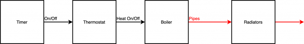
In the single zone system the timer will send an ‘on’ signal to the thermostat if the time and date match the user inputted values or if the heating is set to always on. It is common for the timer and thermostat to be integrated into a single module.
The thermostat will send on ‘on’ signal to the boiler if the measured temperature is below the user desired temperature.
The boiler heats the water in the pipes, which is pumped to the radiators in each room. Usually each radiator has a local thermostat to control the heat in the particular room.
The radiator nearest to the thermostat does not have a local thermostat as the room that it is located in is used by the main thermostat to set the global temperature. This is why it is important to locate your temperature sensor in the same room as your thermostat in this kind of system.
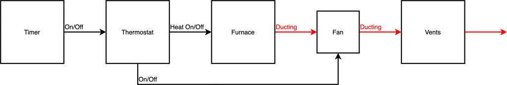
Single zone with furnace only
In the single zone system the timer will send an ‘on’ signal to the thermostat if the time and date match the user inputted values or if the heating is set to always on. It is common for the timer and thermostat to be integrated into the same module.
The thermostat will send on ‘on’ signal to the furnace if the measured temperature is below the user desired temperature. The thermostat also controls the fan and can be set to ‘on’ or ‘auto’ depending on user requirements.
The furnace heats the air which is delivered to the rooms through air ducts. Some systems use return air ducts, which have been omitted from this diagram for clarity.
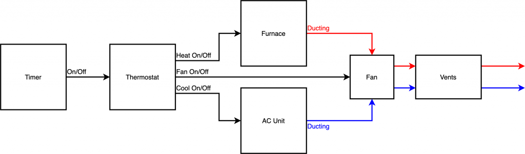
Single zone with furnace and AC
In the single zone system with integrated AC, the timer will send an ‘on’ signal to the thermostat if the time and date match the user inputted values or if the heating/AC is set to always on. It is common for the timer and thermostat to be integrated into the same module.
The thermostat will send on ‘on’ signal to either the AC unit or furnace depending on whether the measured temperature is above or below the set temperature. The thermostat also controls the fan and can be set to ‘on’ or ‘auto’ depending on user requirements.
The furnace heats the air and the AC unit cools the air, which is delivered to the rooms through air ducts. Some systems use return air ducts, which have been omitted for clarity.
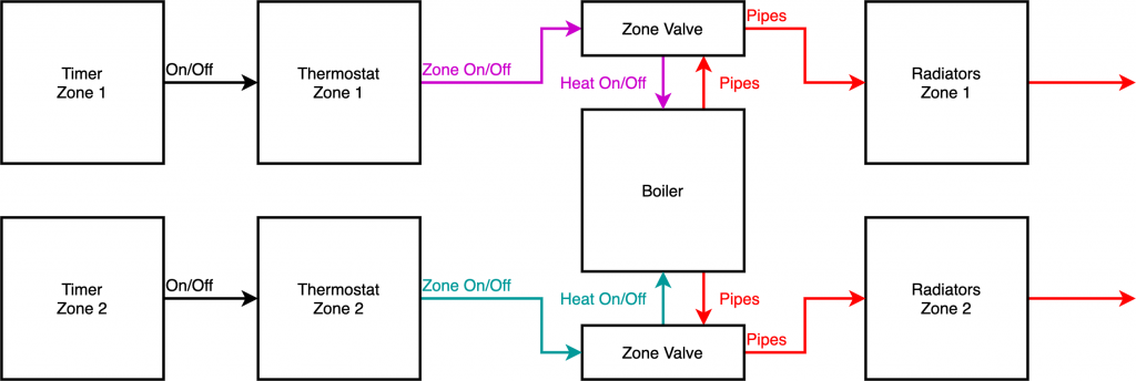
Two zone with boiler
In system that uses a boiler to heat multiple zones there needs to be a thermostat and timer for each zone. Each thermostat and timer functions in the same way as a single zone, except the ‘on’ signal is passed to a zone valve instead of the boiler.
When a zone valve receives the ‘on’ signal, it opens and allows hot water to flow to the radiators in that zone. It also sends an ‘on’ signal to the boiler.
All zone valves in the system are connected globally to the boiler so that if any of the valves are open, the boiler will be on.
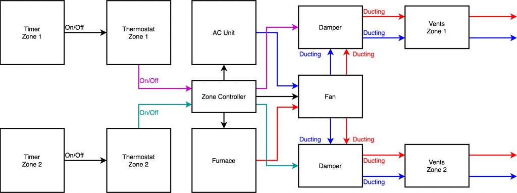
Two zone with furnace and AC
In system that uses a furnace to heat or cool multiple zones there needs to be a thermostat and timer for each zone. The ‘on’ signal from each thermostat is sent to a zone controller.
The zone controller switches on the AC unit, furnace, air duct dampers and fan depending on the requests it receives from each thermostat.
If you wish to convert a system like this, the easiest way is to leave your zone controller installed and simply replace the thermostats with relay switches. You do not need to worry about the complexities of the zone control system.
Choose a configuration
You now hopefully have a good idea about the hypothetical configurations of HVAC system. Please take the time to research your own system and it would be a good idea to create a diagram to match your system.
For this tutorial I will be building a system to cover a two zone system with both heating and cooling ability. I have a dual zone system with a hot water boiler and will be adding a small standalone AC unit in the master bedroom controlled by a smart plug.
The only real difference between my system and a HVAC system using ventilation with respect to Home Assistant, is that I do not require a fan.
However I will include all of the additions including the Home Assistant code and setup for fan control for the benefit of my American friends who are more likely to be using a ventilation based system.
System modification
First let’s take a recap on one of the systems described earlier, the system that is currently operating in my house.
Don’t worry if your system is different, the aim of this tutorial is to give you a full understanding so that you know how you should configure your own system.
Now let’s look at how we will modify this system in order to integrate it with Home Assistant. In mostly all cases (including if you wanted to install a commercially available thermostat) we simply need to replace the thermostat(s) with relay switches and add some method of measuring temperature.
The following diagram shows the system that I will be building. My existing system is shown in the light grey box. The thermostat/timer modules have been removed and replaced with the Home Assistant components.
I have also added a standalone AC unit that I will put in the master bedroom, which can be switched on and off with a smart plug. However this could also be an integrated AC unit that is connected to your ventilation system and switched on and off with an additional relay switch.
There is also a desk fan connected to another smart plug shown in dotted lines. This serves no purpose in my installation but is representative of the fan found in ventilation type systems.
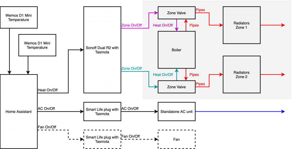
The most important thing to understand here is the inputs and outputs required for Home Assistant, which are common across all types of installation.
Regardless of how your system differs from mine, a Home Assistant thermostat build will fundamentally consist of the following entities.
- Temperature sensor(s)
- Heat/cool on/off relay switch(s)
- Fan switch (for systems with a fan)
Hardware Entities
I will be using the following hardware to run the system, each will be configured as an entity in Home Assistant.
- 1 x Wemos D1 Mini and DHT22 temperature sensor for the downstairs zone
- 1 x Wemos D1 Mini and DHT22 temperature sensor for the upstairs zone
- 1 x Sonoff Dual R2 switch with two relay switches to control each of the zone valves and boiler.
- 1 x Smart Life smart plug to control an AC unit
- 1 x Smart Life smart plug to control fan
All of my devices will be flashed with Tasmota and controlled in Home Assistant using MQTT. If you don’t know what Tasmota is, be sure to check out this post.
Wiring
The wiring found in different systems will not necessarily be the same, therefore it is most important that you have a full understanding of how your system is wired.
In this section I will cover the easiest method of replacing the old thermostats, which will probably be applicable to most folks wanting to build a DIY thermostat. I will also cover an alternative method that I will be using to build my system, primarily to give an idea for an alternative method. There are some benefits to this method at the expense of a slightly more complex installation.
Replacing the thermostat
The easiest way to install your DIY thermostat is simply to replace your existing thermostat(s) with relay switches that can be controlled with Home Assistant.
The existing thermostat
Let’s take a look how to do this, here is the main thermostat in my house that controls the downstairs heating zone. This thermostat has the timer integrated and has switch contacts on the back that open and close to turn the zone valve on and off.
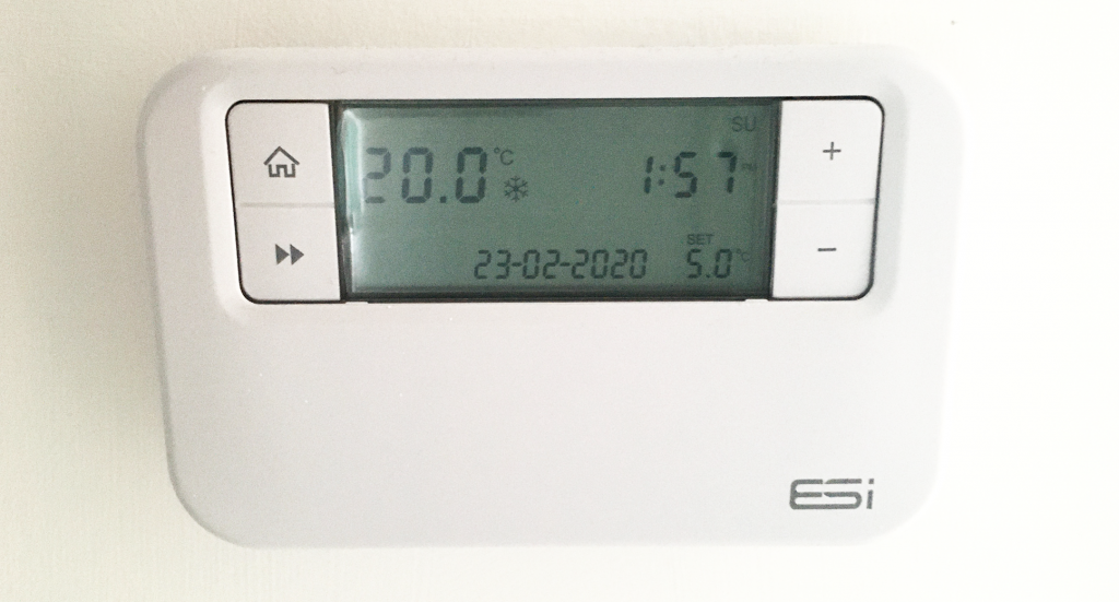
When the thermostat turns the zone valve on, it opens in order to allow the hot water to flow to the radiators downstairs and it also sends a signal to the boiler to switch the heat on.
In a single zone system it would work in exactly the same way, however the zone valve would be omitted and the thermostat would simply control the boiler/furnace heat directly.
Thermostat switch
If we take the unit off the wall we can see that the wiring is very simple. There are just two wires connected to the back and if we short these wires together, the zone will turn on.
WARNING: These cables carry the full mains voltage and could give you a LETHAL electric shock.
DO NOT attempt to modify your HVAC system if you do not fully understand what you are doing. I would advise that you do not attempt any modification to your HVAC system without consulting a certified engineer.
DO NOT touch nor attempt to modify any household wiring without turning off the main power supply. The information here is provided for educational benefit only, I accept no responsibility for injury or damage caused due to information provided on this website.
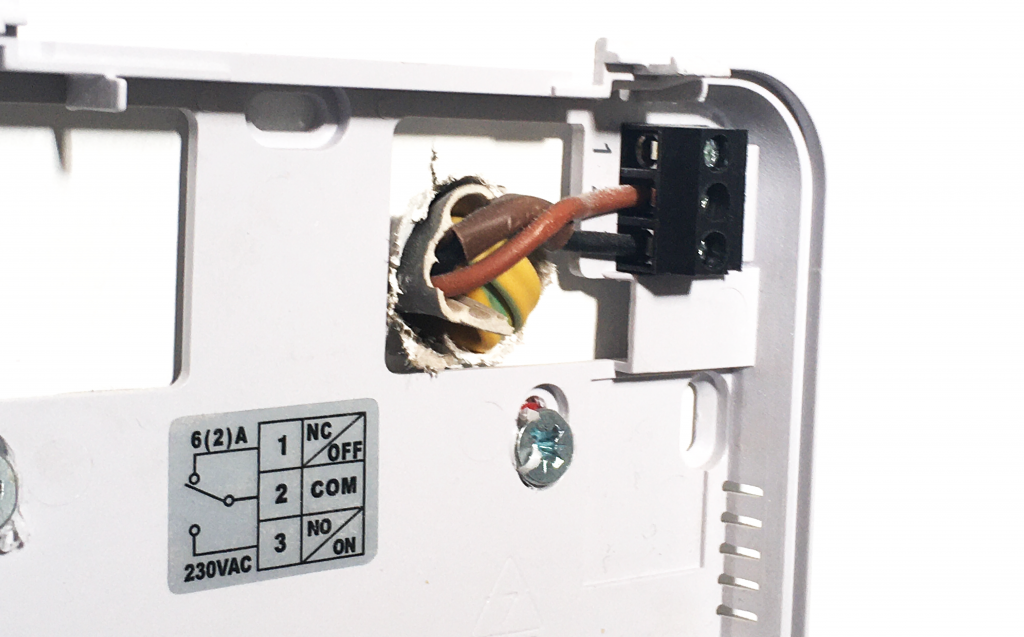
In order to replace the existing thermostat, we simply need to connect these wires to a relay switch that can be controlled by Home Assistant.
You may find additional wiring here for AC or the fan, in which case you can also connect these to separate relay switches for your AC and fan functions.
The power problem
The main issue with simply replacing the existing thermostat is that in many installations there is no power provided. The wires that connect to the back of the thermostat are for switching only. There are however several solutions to this problem.
Battery Power
The existing thermostat has a battery that operates the electronics inside. This low voltage is enough to switch on and off a mechanical relay switch inside the unit. This also electrically isolates the control electronics from the heating system.
You could of course adopt this same technique with your own system. My suggestion here would be to use a Wemos D1 Mini connected to a DHT22 temperature sensor and a relay module.
Both the Wemos D1 Mini, temperature sensor and relay module could be all be powered from 5V sourced from a battery. The disadvantage is of course having the change the battery.
Add a power cable
In addition to your Wemos D1 Mini, temperature sensor and relay module, you could add a 5V switching power supply and run a power cable to the location of your old thermostat.
This is dependant on whether or not you have a convenient place to run the power from. If you have a wall socket nearby you could run the power from there to the thermostat.
Use USB power
If you do have a plug socket located nearby you could just plug in a USB charger and run the USB cable to the location of the thermostat.
This is a safer option compared with running a mains power cable and using a 5V switching power supply module. This is the method that I would most recommend in order to minimise exposure to mains electrical current.
You could either just run the USB cable directly or if you are willing to invest the time, you could hide the wire inside the wall.
Repurpose the existing wires
If you know the location where the wires from the thermostat terminate, you could repurpose them as power cables. This is how the Nest thermostat delivers power to the pretty looking wall control unit.
In the most simplistic cases these wires connect to the switch on the boiler/furnace, however they may also run to a junction box. You would need to install your relay module in the place where the wires terminate and then reconnect these wires to the mains power supply.
This would make the wires in the existing thermostat into a live an neutral, which you could connect to a 5V switching power supply module to run your Wemos D1 Mini.
The benefit of this is you won’t have any wires on show and you do not need to go to the trouble of installing any wiring. However this method requires knowledge of how the home electrical system works and should not be attempted if you do not fully understand how to implement it.
Direct connection
Another way to wire in to your existing system is to connect your relay switches in the location where the existing thermostat wiring terminates.
This is a similar to the method to repurposing the existing wiring, however we will not make any changes to the existing wiring and instead we shall locate our temperature sensors near a USB power source.
Benefits
This is the route I have chosen and the reason being there is already power in this location. In most cases the thermostat wiring will terminate either at the boiler/furnace, zone valves, zone controller or a junction box. All of these require power, therefore we don’t have the power problem.
It also does not require any changes to the existing wiring so is suitable either if you live in rented accomodation of if you do not want to interfere with the existing system. I wanted to minimise the work required to put the system back to how it was in the event of selling my house.
There is also plenty of space in this location as I am not confined to a wall box. This means I can use one of the Sonoff switches, which has the benefits of an integrated mains to 5V power supply and comes already housed in its own case.
In my system I have a junction box next to the zone valves. Both thermostats terminate here and there is also power for the valves that I can tap for the Sonoff switch. I can simply wire the Sonoff to the junction box and I am done, no need to worry about housing electronics or finding power. If I wish to convert the system back to the original state, I can just remove the Sonoff and reconnect the original thermostat wiring.
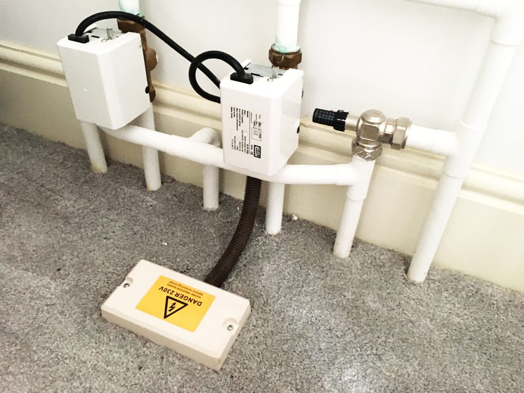
If our thermostat wiring terminates at the boiler/furnace we can also adopt the same strategy and tap the power from the boiler/furnace whilst wiring the Sonoff to the boiler/furnace switch terminals, just like a Google Nest installation. No housing electronics of finding a power supply necessary.
Drawbacks
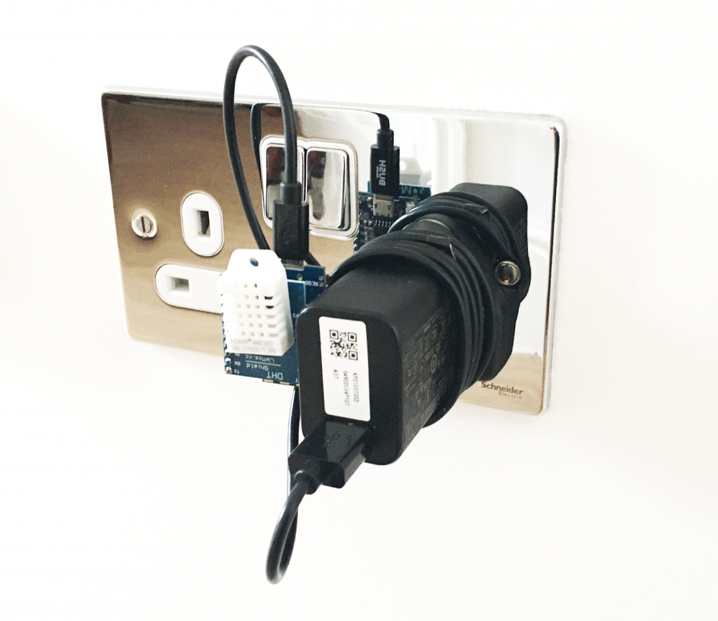
The only downside to this is we cannot incorporate our temperature sensor and relays into a single module as it is almost certainly the wrong location. Therefore for this solution we will use a seperate D1 Mini for each temperature sensor and locate them near the existing thermostats.
However this does have the benefit of being able to hide the temperature sensor inside something more creative than an ugly wall box, or having to make major changes to the existing thermostat installation.
My future plan is to build a smart lamp for the hallway that can be controlled as usual, but that also reports the temperature back to Home Assistant.
For now I have the modules attached to USB chargers, which are plugged in to sockets near the old thermostats.
Wiring schematics
Let’s take a look at the diagrams for some clarity. Firstly we will look at the most basic system for heat only. The system is very simple, the timer thermostat module has a live incoming cable connected to a switch shown in brown.
The following diagrams are just ideas to help you understand the kind of system that exists. It should give you enough of an idea how to design your own system. It is important that you understand how your own system works and then apply some of the ideas here.
Non-smart single zone
When the thermostat wants to switch the boiler on, its internal relay closes and the mains current travels along the black wire to the boiler/furnace, switching it on. Note that there is only a live and neutral mains connection to the boiler and not to the thermostat.
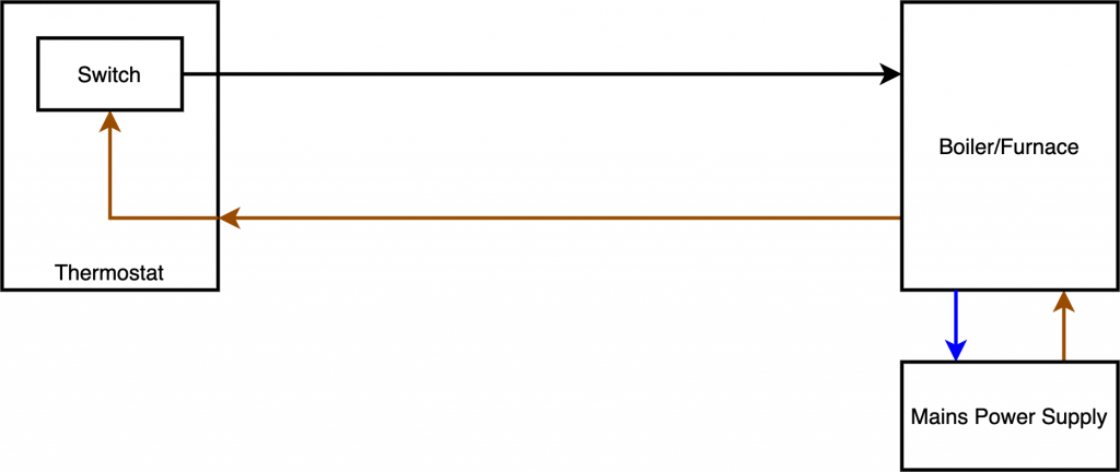
All we need to do in order to connect this to Home Assistant is replace the thermostat with a smart relay switch and give the smart relay a power source.
Single zone with Sonoff Basic, Wemos D1 Mini and DHT22
We can use a smart switch like the Sonoff basic to control the signal to the boiler/furnace. This installation is better suited next to the boiler/furnace as we need the mains voltage to power the Sonoff Basic.
Although if you wanted to directly replace your existing thermostat, you could repurpose the existing wiring as explained earlier.
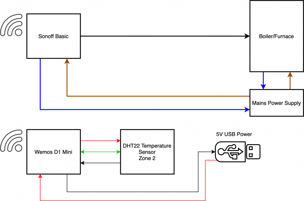
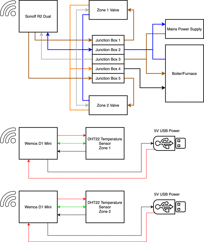
In order to feed the temperature to Home Assistant we can use a seperate low voltage system consisting of a Wemos D1 Mini and DHT22 temperature sensor. This can be powered from USB as shown in the diagram, or from a battery.
The thinner red and black lines show the 5V positive and negative connections. The green lines show data or a control signal.
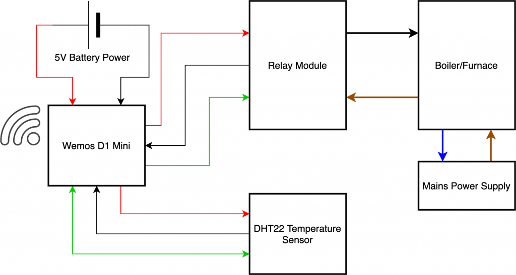
Single zone with Wemos D1 Mini, DHT22 and relay module
This configuration is suitable for replacing an existing thermostat as no mains voltage is required. The wires behind the old thermostat are switched by a relay module controlled by the D1 Mini.
The D1 Mini also receives the temperature readings from a DHT22 sensor. Home Assistant can control the relay module and read the temperature from the single module when using Tasmota.
The D1 Mini can be powered from a battery as shown here in this diagram or from USB.
Non-smart dual zone
The dual zone system looks a lot more complicated in the diagram, but it is quite straightforward in its operation. This example features two zones, one upstairs and one downstairs area.
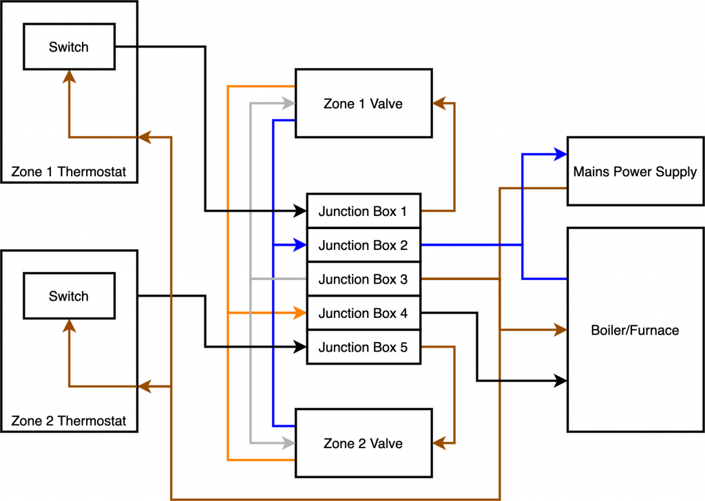
The mains power is globally connected to both zone valves and the boiler/furnace using terminals 2 and 3 of the junction box. Neutral is shown in blue, live is shown in brown but grey is also used for the zone valves. These wire colours reflect the actual colours found in my system, however this may be different in your system depending on your location.
The live connection for the thermostat switches are also connected to terminal 3 of the junction box. When either of the thermostats makes a call for heat, the switch inside the thermostat is closed and the current is delivered to the corresponding zone valve through terminals 1 and/or 5 of the junction box.
When either of the zone valves open, current is delivered down the orange wire through terminal 4 of the junction box to the heat switch in the boiler. This means that if either zone valve is open, the heat will be switched on.
Dual zone with Sonoff Dual R2, Wemos D1 Mini and DHT22
In order to make this system smart, we can replace the two thermostats with a Sonoff Dual R2 or similar, or a pair of relay switch modules. With the thermostats removed, the two relay switches in the Sonoff are connected to terminals 1 and 2 of the junction box.
The Sonoff can also tap mains power from the global mains supply found on terminals 2 and 3. When the relays in the Sonoff close, the zone valves activate and the system behaves the same as it would with the original thermostats.
Home Assistant takes temperature readings from two seperate Wemos D1 Minis connected to DHT22 temperature sensors. These can be powered from any 5V source, such as USB or a battery. This is the configuration I will be building.
Configuring Home Assistant
Now that we have taken a detailed look at all the hardware and covered a variety of possibilities with the configuration, we are ready to setup Home Assistant.
You will need to have Home Assistant installed and configured, plus your devices added and recognized as entities. If you are using Tasmota, I have a detailed guide on how to set it up to auto discover in Home Assistant.
I also have an awesome tutorial on how to build a temperature sensor for Home Assistant using a Wemos D1 Mini and DHT22, so go check it out if you still need temperature sensors.
If you need to configure a Sonoff device for Home Assistant, I would recommend flashing it with Tasmota and setting it up to auto discover.
Set up entities
As previously mentioned we are going to create a system capable of full HVAC control. You can omit any of the elements if it is not applicable to your configuration. Let’s recap on the devices we will be using.
- Sonoff Dual R2 – two switch relays that control each heating zone
- Smart Life plug – to switch on and off a standalone AC unit
- Smart Life plug – to switch on and off the fan (not applicable to my system, but included for those who will need it)
- Wemos D1 Mini + DHT22 – upstairs temperature sensor
- Wemos D1 Mini + DHT22 – downstairs temperature sensor
I have configured Tasmota on all of these devices and they are all showing in Home Assistant as entities. For references, the names are as follows.
- switch.ac – switch for the AC unit
- switch.fan – switch for the fan
- switch.heatupstairs – turn upstairs zone heating on
- switch.heatdownstairs – turn downstairs zone heating on
- sensor.temperaturedownstairs – downstairs temperature sensor
- sensor.temperatureupstairs – upstairs temperature sensor
Setup climate component
Home Assistant has a really good built-in thermostat integration called generic thermostat that we will use for our system. However there is a limitation, it only supports a single zone of either heating or cooling.
In my system there are two zones of heating and one zone of AC (the standalone AC unit in the bedroom). Therefore we will configure three instances of generic thermostat to control each one individually. Then we will tie them together with an automation.
The climate components should be defined in configuration.yaml under climate.
climate:
I have chosen to split my files up, therefore my climate components are defined in a separate file called /climate/generic_thermostat.yaml.
In order to add all of the YAML files within this directory, we need to add the following to our configuration.yaml file.
climate: !include_dir_merge_list climate/
Then we need to create a new directory and add a new YAML file.
/config/climate/generic_thermostat.yaml
If you would rather just keep everything in your configuration.yaml file, simply enter the code after climate: with one level of indentation.
Now we can enter the first instance of generic thermostat in our generic_thermostat.yaml file.
Define first thermostat
First we need to define the platform as generic_thermostat and give it a name. We will start with a thermostat for the downstairs zone.
  - platform: generic_thermostat
    name: Downstairs
Next we need to specify the switch that will control the zone valve for downstairs (or just the boiler/furnace in a single zone system).
heater: switch.heatdownstairs
Then we need to define the sensor that Home Assistant will use for the temperature within this particular zone.
target_sensor: sensor.temperaturedownstairs
We can set a minimum and maximum value for temperature. This will be the operating range of the slider within the thermostat.
min_temp: 15
max_temp: 25
The ac_mode parameter tells Home Assistant whether the thermostat is connected to a heating or cooling device. As this zone is for the downstairs heating we will set this to false.
ac_mode: false
The target_temp parameter is the temperature that the thermostat is trying to achieve. This is only the starting value when Home Assistant loads and will change when you adjust the temperature slider.
target_temp: 20
The cold_tolerance parameter is the value that the temperature must drop by before the switch is turned on. This is relevant for a thermostat setup as a heater. The default of 0.3 degrees C works well with the DHT22 sensor.
cold_tolerance: 0.3
The hot_tolerance parameter is the value that the temperature must increase by before the switch is turned on. This is relevant for a thermostat that is setup to control AC.
hot_tolerance: 0
The initial_hvac_mode parameter is the mode that the thermostat will be set to when first loaded.
initial_hvac_mode: "off"
The away_temp parameter is the temperature that the thermostat will use if Home Assistant detects that you are away. If you do not want to use this feature, just exclude this line of code.
away_temp: 16
You can set the precision of your sensor using the precision parameter. It defaults to 0.5 for celsius and 1 for fahrenheit. As the DHT22 has a precision of 0.1, we can set it accordingly.
precision: 0.1
Now we have entered all of the code for our first thermostat instance and the completed code should look like this.
  - platform: generic_thermostat
    name: Downstairs
    heater: switch.heatdownstairs
    target_sensor: sensor.temperaturedownstairs
    min_temp: 15
    max_temp: 25
    ac_mode: false
    target_temp: 20
    cold_tolerance: 0.3
    hot_tolerance: 0
    initial_hvac_mode: "off"
    away_temp: 16
    precision: 0.1
The thermostat integration is well documented on the Home Assistant website, I would recommend reading about it further on the Generic Thermostat page.
Define second thermostat
Now that we have completed the first thermostat, we can make a copy of the code below on order to make the second instance for the upstairs heating zone.
We need to change the name to Upstairs and also we need to use switch.upstairs in order to control the upstairs heating zone with this thermostat. We also need to use sensor.temperatureupstairs for our temperature reading.
See line 2 to 4:
  - platform: generic_thermostat
    name: Upstairs
    heater: switch.upstairs
    target_sensor: sensor.temperatureupstairs
    min_temp: 15
    max_temp: 25
    ac_mode: false
    target_temp: 20
    cold_tolerance: 0.3
    hot_tolerance: 0
    initial_hvac_mode: "off"
    away_temp: 16
    precision: 0.1
Define the third thermostat
Finally we need to add a third instance of the thermostat in order to control the AC unit in the master bedroom. Again we will make a copy of the code and amend the necessary parameters.
We need to change the name to Upstairs AC and also we need to use switch.ac in order to control the AC unit with this thermostat. We also need to use sensor.temperatureupstairs for our temperature reading. This sensor is located in the same room as the AC unit but if you have yours in a different room, you should add an additional sensor in that room and use it instead.
As this thermostat will be used for cooling and not heating we need to change the ac_mode to true so that the switch is enabled when the heat is above the setpoint. We also need to change the hot_tolerance and cold_tolerance values.
See line 2 to 4, 7, 9 and 10:
  - platform: generic_thermostat
    name: Upstairs AC
    heater: switch.ac
    target_sensor: sensor.temperatureupstairs
    min_temp: 15
    max_temp: 25
    ac_mode: true
    target_temp: 20
    cold_tolerance: 0
    hot_tolerance: 0.3
    initial_hvac_mode: "off"
    away_temp: 16
    precision: 0.1
Now that we have all instances of the climate integration, the file should look something like this.
  - platform: generic_thermostat
    name: Downstairs
    heater: switch.heatdownstairs
    target_sensor: sensor.temperaturedownstairs
    min_temp: 15
    max_temp: 25
    ac_mode: false
    target_temp: 20
    cold_tolerance: 0.3
    hot_tolerance: 0
    initial_hvac_mode: "off"
    away_temp: 16
    precision: 0.1

  - platform: generic_thermostat
    name: Upstairs
    heater: switch.upstairs
    target_sensor: sensor.temperatureupstairs
    min_temp: 15
    max_temp: 25
    ac_mode: false
    target_temp: 20
    cold_tolerance: 0.3
    hot_tolerance: 0
    initial_hvac_mode: "off"
    away_temp: 16
    precision: 0.1

  - platform: generic_thermostat
    name: Upstairs AC
    heater: switch.ac
    target_sensor: sensor.temperatureupstairs
    min_temp: 15
    max_temp: 25
    ac_mode: true
    target_temp: 20
    cold_tolerance: 0
    hot_tolerance: 0.3
    initial_hvac_mode: "off"
    away_temp: 16
    precision: 0.1
Awesome! Now we have completed all of our instances of the climate integration, go ahead and save the YAML file.
Setup Automation
There are some important rules that we must setup in order to make sure our system functions safely and that no damage is caused.
This step is important and should not be skipped or you may cause damage to your HVAC system.
We also need to add some automation to control the fan as this is not included within the generic thermostat module. Firstly let’s summarize the rules that needs to be created.
- The heat must be disabled if the AC in enabled
- The AC must be disabled if the heat is enabled
- The fan must run if either AC or heat is enabled
- The fan must stop if neither the heat or AC is enable
The automation rules should be entered into your configuration.yaml file under automation.
automation:
I have chosen to split my files up, therefore my automation component for climate is defined in a separate file called /automation/climate_rules.yaml.
In order to add all of the YAML files within this directory, we need to add the following to our configuration.yaml file.
automation: !include_dir_merge_list automations/
Then we need to create a new directory and new YAML file.
/config/automations/climate_rules.yaml
If you would rather just keep everything in your configuration.yaml file, simply enter the code after automation: with one level of indentation.
Add fan turn on rule
Now we can enter the climate automation rules in our climate_rules.yaml file. First we will create a series of automations which turn on the fan if either of the heat zones or the AC unit are turned on.
  - alias: "Turn on fan if heat downstairs"
    trigger:
        platform: state
        entity_id: switch.heatdownstairs
        to: 'on'
    action:
        service: switch.turn_on
        entity_id: switch.fan

  - alias: "Turn on fan if heat upstairs"
    trigger:
        platform: state
        entity_id: switch.heatupstairs
        to: 'on'
    action:
        service: switch.turn_on
        entity_id: switch.fan

  - alias: "Turn on fan if AC on"
    trigger:
        platform: state
        entity_id: switch.ac
        to: 'on'
    action:
        service: switch.turn_on
        entity_id: switch.fan
Add fan turn off rule
Next we will create a series of automations that switch off the fan if all of the heating zones and the AC are switched off. It is important that the fan does not switch off if only one of the climate elements are turned off.
The fan will only be turned off if both other switches are off. Therefore the three rules we need to create are as follows.
When heat zone one is turned off, check if heat zone two AND the AC are turned off. If both are off, turn off the fan.
When heat zone two is turned off, check if heat zone one AND the AC are turned off. If both are off, turn off the fan.
When the AC is turned off, check if heat zone one AND heat zone two are turned off. If both are off, turn off the fan.
We can achieve this using the and condition. We must create a separate event the fires for each heating zone switch and the AC switch. When one switch is turned off, the event will check if the other two switches are both in the off state using the and condition.
  - alias: "Turn off fan if heat downstairs turned off"
    trigger:
        platform: state
        entity_id: switch.heatdownstairs
        to: 'off'
    condition:
      - condition: and
        conditions:
          - condition: state
            entity_id: switch.heatupstairs
            state: "off"
          - condition: state
            entity_id: switch.ac
            state: "off"
    action:
        service: switch.turn_off
        entity_id: switch.fan

  - alias: "Turn off fan if heat upstairs turned off"
    trigger:
        platform: state
        entity_id: switch.heatupstairs
        to: 'off'
    condition:
      - condition: and
        conditions:
          - condition: state
            entity_id: switch.heatdownstairs
            state: "off"
          - condition: state
            entity_id: switch.ac
            state: "off"
    action:
        service: switch.turn_off
        entity_id: switch.fan

  - alias: "Turn off fan if AC turned off"
    trigger:
        platform: state
        entity_id: switch.ac
        to: 'off'
    condition:
      - condition: and
        conditions:
          - condition: state
            entity_id: switch.heatupstairs
            state: "off"
          - condition: state
            entity_id: switch.heatdownstairs
            state: "off"
    action:
        service: switch.turn_off
        entity_id: switch.fan
AC/Heat turn off rule
We also need to add a rule that will switch the AC and both heating zones off if the fan is turned off manually.
This will ensure that if for some reason the fan is turned off, the AC and heating zones do not continue to run.
  - alias: "Turn AC off if upstairs heat on"
    trigger:
        platform: state
        entity_id: climate.upstairs
        from: 'off'
    action:
        - service: climate.turn_off
          entity_id: climate.upstairs_ac

  - alias: "Turn AC off if downstairs heat on"
    trigger:
        platform: state
        entity_id: climate.downstairs
        from: 'off'
    action:
        - service: climate.turn_off
          entity_id: climate.upstairs_ac
Toggle heat and AC rule
Lastly we want to ensure that the AC thermostat and both heating thermostats toggle so that they cannot be switched on at the same time.
This means that when you switch either heating thermostat on, the AC thermostat switches off and if you switch the AC thermostat on, the heating thermostats switch off.
  - alias: "Turn AC off if upstairs heat on"
    trigger:
        platform: state
        entity_id: climate.upstairs
        from: 'off'
    action:
        - service: climate.turn_off
          entity_id: climate.upstairs_ac

  - alias: "Turn AC off if downstairs heat on"
    trigger:
        platform: state
        entity_id: climate.downstairs
        from: 'off'
    action:
        - service: climate.turn_off
          entity_id: climate.upstairs_ac

  - alias: "Turn heat off if AC is on"
    trigger:
        platform: state
        entity_id: climate.upstairs_ac
        from: 'off'
    action:
        - service: climate.turn_off
          entity_id: climate.upstairs
        - service: climate.turn_off
          entity_id: climate.downstairs
Superb! All the code is finally complete so we can go ahead and and save the YAML file.
Create the lovelace cards
Well done if you got this far in the tutorial! The hard bit is complete and now the fun part! We can create the lovelace cards and finally test our our new thermostat!
We will create the cards using the UI editor and the built-in thermostat card. From the overview page, click on the three dots and then configure UI in the top right-hand corner of the page.
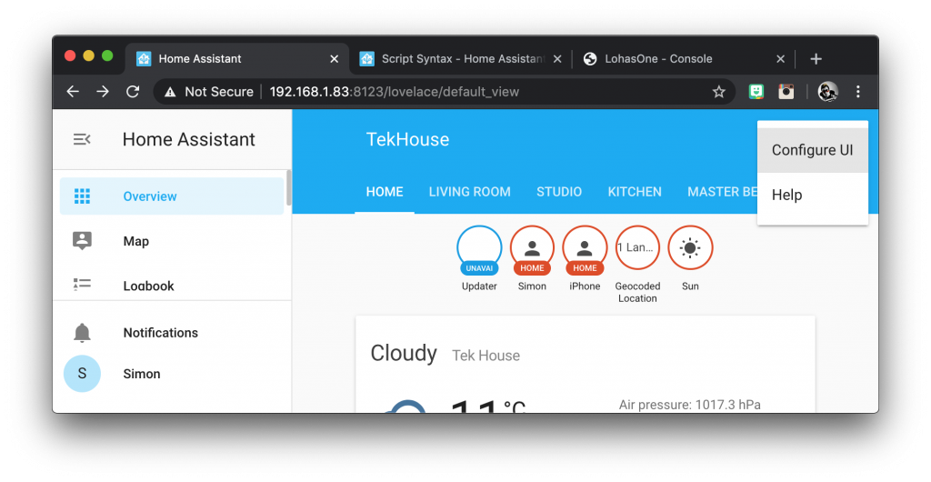
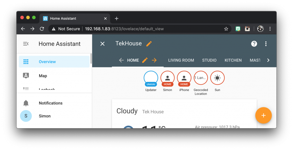
This will switch on the UI editor mode. I will create a new tab called thermostat for the cards but you can put them anywhere you like.
Create the entity card
Once on the desired tab, click the orange circle with the plus towards the bottom right of the screen and choose the entity card.
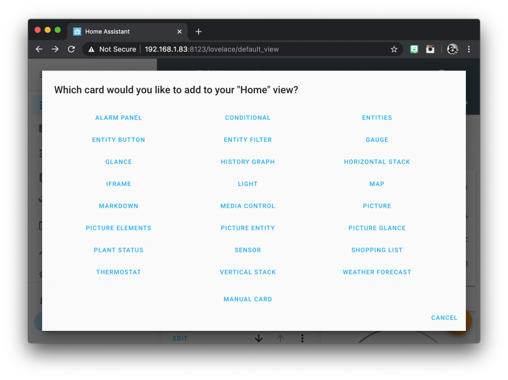
This card will contain all of the entities used in our thermostat system. It is not actually required for functionality but I would highly recommend it in order to check everything functions as expected.
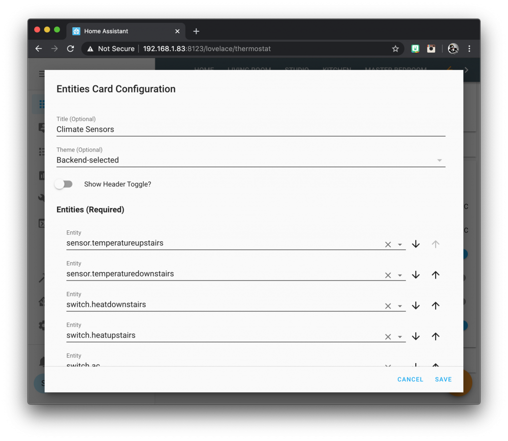
Give the entity card a title, I called mine climate sensors. Switch off the show header toggle switch as it is not needed. In the entities list we need to enter all of the entities used in the system. Once you are done click save.
- switch.ac – switch for the AC unit
- switch.fan – switch for the fan
- switch.heatupstairs – turn upstairs zone heating on
- switch.heatdownstairs – turn downstairs zone heating on
- sensor.temperaturedownstairs – downstairs temperature sensor
- sensor.temperatureupstairs – upstairs temperature sensor
Create the thermostat cards
Once you are back to the overview page, click on the orange circle with the plus again to add another entity. This time we will add a thermostat card.
Select the first climate entity in the entity box, in this case I chose climate.downstairs. Enter the name you wish to be displayed on the card under in the name box. Once you are done click save.
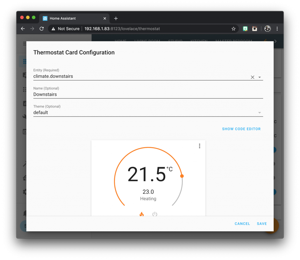
Repeat this process and create another two cards for the climate.upstairs and climate.upstairs_ac entities. Now you should have a total of four cards on your thermostat tab.
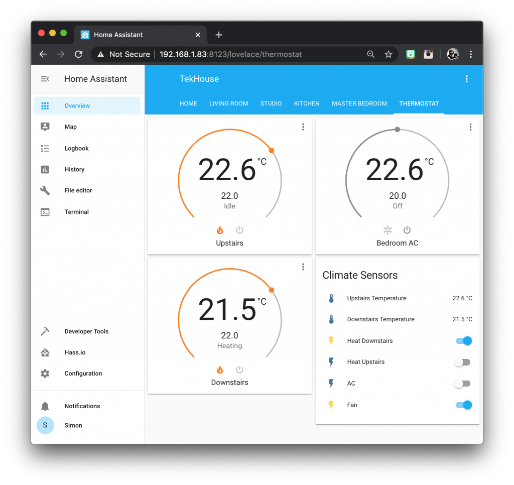
Conclusion
That’s it, we are all done! Congratulations for making it to the end of this huge tutorial! Time to open that bottle of bubbly and celebrate whilst you forget about your HVAC system. Home Assistant will take care of it now for you!
Personally I am very pleased with the thermostat integration in Home Assistant, so much so that I was inspired to make such a long tutorial.
It would be great to see an integrated thermostat that can handle multiple zones and both heating and cooling in a future version of Home Assistant.
However with a little automation YAML it is possible to get the exact functionality that a sophisticated HVAC system needs.
Thanks for visiting and taking the time to read my post, don’t forget to check out some more cool articles!
Thanks so much for visiting my site! If this article helped you achieve your goal and you want to say thanks, you can now support my work by buying me a coffee. I promise I won't spend it on beer instead... 😏

Great tutorial, helped me a lot in setting home assistant for my thermostat purposes at home.
Very glad to hear it Johan and thanks for visiting!
This is great, exactly what I needed. Many thanks!
John
Great guide, do you need a bridge for the sonoff devices or do they connect direct to the wifi router?
Thanks
Michael
Thanks for visiting Michael, Sonoff devices in this example will connect directly 🙂
Dear sir my current connection is as in the diagram on Non-smart single zone
I have a siemens thermostat RDD10.1 (with battery) what I don’t understand is how I will connect the sonoff to accomplish what is shown on the next diagram.
I can supply the sonoff with phase and neutral but then what it need to send back to the boiler/furnace just the phase an it will work that way?
From my research I have found that this type of switch on the thermostat is called “Dry switch”.
But sonoff is made to send both phase and neutral to supply power to devices.
Do I have to modify the sonoff to accomplice what is shown in the diagram?
Thank you for this Great tutorial.
Great article 👍 I recently installed a Wiser system but it only has two zones so I’m going to add a third zone. Out of interest did you set up a heating schedule with your system and/or add TRVs? Thanks again for the detailed article!
TRVs are something that I am in the process of adding, Sonoff recently sent me their new offering, it’s pretty good! See here: https://siytek.com/sonoff-trvzb-review/