Welcome to the definitive guide to the ESP8266, a fabulous low cost chip that has become ubiquitous in the maker and IoT community.
Here you will find everything you need to know to get started with building and programming your own WiFi-enabled devices with the awesome ESP8266 chip.
The ESP8266 and ESP8285 chips from the Chinese manufacturer Espressif are 32-bit microcontrollers with an integrated WiFi interface.
Due to their very reasonable cost, development boards and ‘hackable devices’ containing these chips are abundant!
Normally, the small ESP modules are sold with the so-called “AT firmware”, which allows them to be used in a similar way to analog modems or Bluetooth modules.
However you can also flash your own programs directly onto the ESP chip. With prices starting at €1.50, the ESP modules are a very inexpensive choice for tinkering and maker projects.
Different Types of ESP8266 Module
Due to the low cost and functionality of the ESP8266, there have been quite a number of variations of module produced that can be easily implemented into a maker project.
It use useful to know about some of the subtle differences between the modules, for example the CHIP_EN pin is often called CHIP_PU, CH_PD, ENABLE or EN for short.
Many I/O pins can only be used to a limited extent, depending on the module hardware.
To get more completely free I/O pins, I you can use an I/O expander with an I²C interface, like the PCF8574 , or shift registers like the 74HC165 or 74HC595 .
There are also serial ADCs that are really easy to use and measure much more accurately, for example the MCP3208, although the ESP8266 does have a built in ADC.
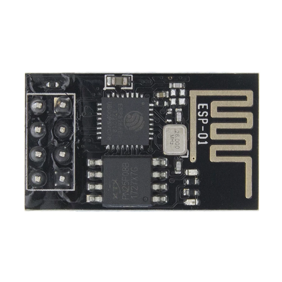
ESP-01 and ESP-1 Modules
The ESP-01 module is based on the ESP8266. It is sold with 512 kbyte Flash (in blue) or 1 Mbyte (in black).
It features a red and blue LED, which indicate that there is power and activity on the Tx pin respectively.
The ESP-01S also has 1 MB Flash. It has additional pull-up resistors on the Enable and Reset pins but only has the blue Tx LED on GPIO2.
The ESP-1 module is based on the ESP8285. It has 1 MB flash memory and a cover for shielding. It only has a blue LED on the Tx pin.
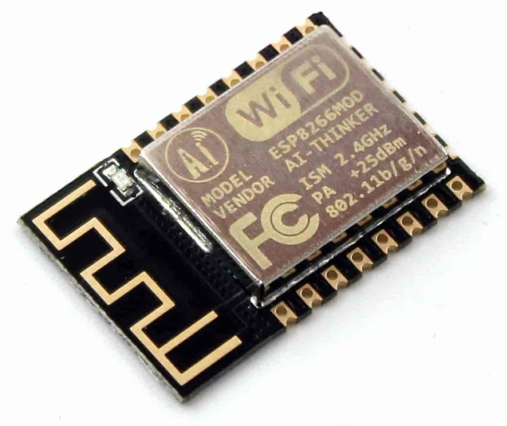
ESP-07 and ESP-12 Modules
The ESP-07 module has a 1 MB flash chip, a ceramic antenna and a socket for external antennas.
There is a red power LED and a blue Tx LED connected to GPIO2. The capacitor located next to the antenna port should be removed when using an external antenna.
The ESP-07S module has 1 MB Flash, no LEDs and no antenna. It must be operated with an external antenna.
The ESP-12S, ESP-12E and ESP-12F models have 4 MB Flash and a conductor loop as an antenna.
The blue LED is attached to GPIO2, there is no power LED. The 12E and 12F models have a third row of pins that are not connected.
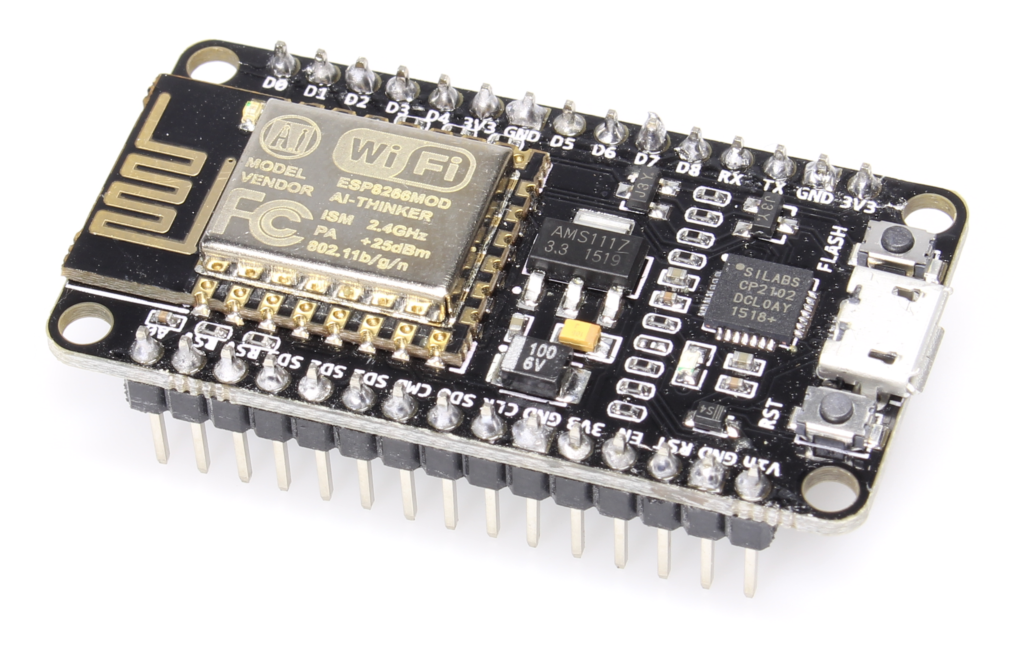
NodeMCU board
The NodeMCU board consists of an ESP-12 module with voltage regulator and USB-UART interface (CH-340) and the flash memory is 4 megabytes in size.
You can operate the board either by using using the 3.3V or 5V inputs, plus you can also power the board from the USB cable.
A diode prevents current from the 5V Input flowing to the USB input. The voltage regulator current rating of 300mA with an input voltage of 5V, which is useful to know if you will be using it to power external devices.
The board isn’t really suitable for battery operation since its voltage regulator has a quiescent current consumption of around 10 mA.
The reset line and GPIO0 can be controlled by the USB-UART, which means the firmware can be flashed without the need to put the board into bootloader mode manually.
Alternatively, you can activate the firmware upgrade mode manually by pressing both buttons and then releasing the reset button first.
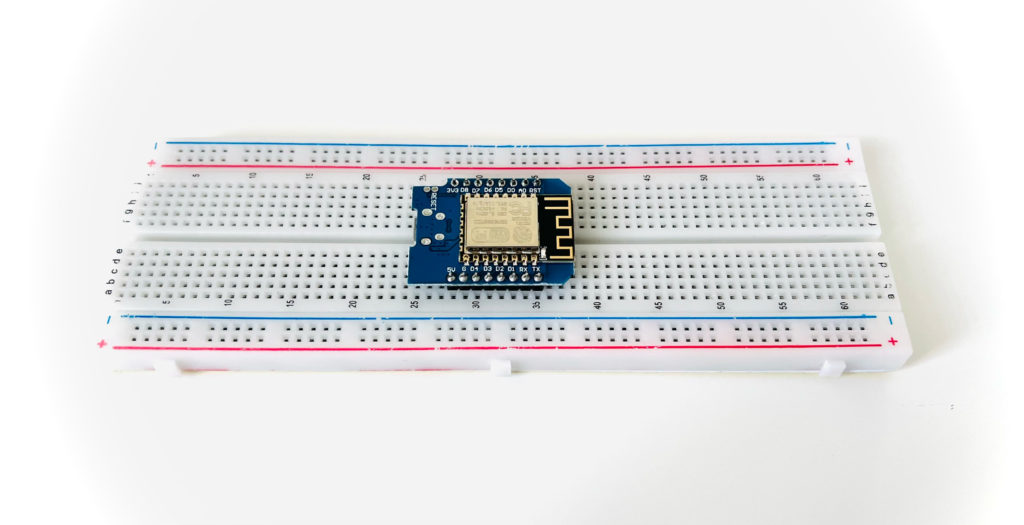
Wemos D1 Mini Board
The Wemos D1 Mini Board is available in the following versions:
| Version | ESP chip | Flash MByte | LED on GPIO2 | Antenna | Battery Charging |
|---|---|---|---|---|---|
| Wemos D1 Mini Lite V1 | ESP8285 | 1 | Yes | Conductor loop | No |
| Wemos D1 Mini V2 | ESP-12 module (ESP8266) | 4 | No | Conductor loop | No |
| Wemos D1 Mini V3 | ESP8266 | 4 | Yes | Conductor loop | No |
| Wemos D1 Mini Pro V1 | ESP8266 | 16 | Yes | Ceramic antenna and ext. antenna connector | No |
| Wemos D1 Mini Pro V2 | ESP8266 | 16 | Yes | Ceramic antenna and ext. antenna connector | Yes |
All of the boards have the same dimensions with the exception of the Wemos D1 Mini Pro V2, which is a little longer due to an integrated Li-ion battery charge controller.
All versions have a USB-UART (CH-340) and a low-dropout voltage regulator. All free I/O pins of the ESP chip are accessible, but not the CHIP_EN pin.
You can operate the board either by using using the 3.3V or 5V inputs, plus you can also power the board from the USB cable. A diode prevents current flows from the 5V input to the USB port.
Depending on the variant, the quiescent current consumption of the board ranges between 200 and 1600 µA.
The voltage regulator is just sufficient for the WLAN chip, with minimal headroom to connect external devices, 50 mA at 5V. To improve reliability you can connect a 100 µF capacitor between 3.3V and GND.
The reset button pulls the reset pin directly to GND without a current limiting resistor and there is no button. The boards have the same automatic reset as the NodeMCU board.
The analog input A0 is equipped with a voltage divider (220kΩ + 100kΩ) so that voltages up to 3.2 V can be measured.
ESP8266 Power Supply
For reliable operation, the ESP chip requires a stable power supply between 2.8 and 3.6 volts with a current consumption of 5 µA to 430 mA.
An inadequate power supply is the most common cause of malfunctions and it can even lead to the destruction of the chip.
It is also important to use a good voltage regulator with a quick response that can compensate for extreme current fluctuations .
In order to improve power supply stability, a 100 µF capacitor can be added directly across the VCC and GND pins of the ESP module.
Using Batteries To Power The ESP8266 Modules
Boards with a USB interface and voltage regulator are not well suited for economical operation on batteries, as they draw a lot of quiescent current.
For battery powered applications, boards such as the ESP-12F, which have fewer external components can be a better choice.
You should of course look for a voltage regulator with low quiescent current so that the batteries are not drained whilst idling.
The currently capability of the voltage regulator should also be 500mA as the ESP needs the best part of this current at times.
Lithium and lead batteries must also be equipped with over discharge protection so that they are not discharged past a safe level. Some lithium batteries already contain such a protective circuit.
ESP8266 Deep Sleep Mode
In deep sleep mode the current consumption of the ESP chip (including flash) is around 20 µA. The WLAN connection will be interrupted. The RTC (clock) continues to run, but less precisely than in normal operation.
When using Arduino, you can activate deep sleep with the following code:
ESP.deepSleep(60000000);
delay(100);
As a parameter you can specify in how many microseconds before the chip should wake up again, with a maximum value of 71 minutes.
A value of 0 lets the chip sleep forever, or until the next hardware reset.
When using the wakeup timer, the timer output GPIO16 must be connected to the RESET input of the chip.
Since the timer is clocked by a temperature-dependent RC oscillator, the time can deviate by up to two percent, which can translate to a 30 minute inaccuracy per day.
During power cycling the contents of the RAM and the additional 512 bytes of memory for the RTC are lost. However the RTC memory will remain intact throughout deep sleep.
ESP8266 Power Down Mode
In power-down mode the chip is completely switched off and only a small leakage current of about 5 µA flows.
This mode is triggered by a falling edge at the CHIP_EN input, but only after the firmware has been initialised. If CHIP_EN is pulled low too early, the chip will draw about 2.5 mA.
A rising edge at the CHIP_EN input causes the power-down mode to be exited and the firmware to be restarted.
Unfortunately, many modules contain a pull-up resistor on this pin, which increases the current consumption to around 20 µA.
While the RESET input is held LOW, the chip draws about 23 mA. The RESET input is therefore not suitable for saving power.
Using a USB UART Cable With ESP8266
For ESP8266 modules without a USB port, you will need a USB-UART cable or adapter to connect it to the computer.
It is important that the USB-UART adapter has a 3.3V power output in order prevent damage to the ESP8266.
Many USB-UART interfaces use the Chinese CH340 chip, which will likely require a driver. The driver for the Chinese CH340 and CH341 chips can be downloaded directly from the manufacturer’s website .
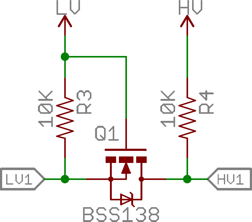
Connection To A 5V Microcontroller
The ESP chip can handle a maximum of 3.6V on all pins so connecting it to a 5V microcontroller will likely cause a problem.
The easiest way to solve this problem is by using a simple level shifter circuit.
You can either get a small pre-made module, or you can make your own using using a BSS138 and a couple of resistors.
ESP8266 Flash Memory
The ESP8266 executes its firmware from internal RAM after copying it from flash block by block.
The chip can address up to 16MB of flash memory, but can only use a maximum of 1MB as program memory. The base firmware occupies about a quarter of it.
The ESP8266 supports the following types of access to the flash memory:
- QIO uses 4 lines for reading and writing
- QOUT uses 4 lines for reading but only 1 line for writing
- DIO uses 2 lines for reading and writing
- DOUT uses 2 lines for reading but only 1 line for writing
Of these four variants, the ones that work for a particular module depends on the built-in memory chip. Most can DIO with 40Mhz. To change the access parameters you have to modify the firmware.
The ESP8285 has 1 MB Flash internally, which only supports DOUT with 40MHz. The chip has two more I/O pins free for this, GPIO9 and GPIO10.
Uploading Firmware to the ESP8266
The ESP chip contains an immutable bootloader that allows firmware upgrades through the serial port. To update the firmware the chip must be started in bootloader mode.
Many modules with an onboard USB-UART are connected in such a way that they can set the GPIO pins to the correct state without user input during the uploading of firmware.
However some modules do not have this feature, in which case the GPIO0 pin should be pulled LOW for uploading firmware and pulled HIGH when starting normally.
The resistor in front of GPIO0 protects against short circuits if the pin is programmed as an output. The wakeup jumper must be connected when using deep sleep mode with wakeup timer.
What’s Next?
You can check out my guides for flashing NodeMCU to ESP8266 or how to setup and use Arduino with ESP8266 for further information on how to flash firmware.
Also you should check out my other ESP8266 tutorials! My favorite ESP8266 board is the Wemos D1 Mini, you can read all about it here, or check out some of my more specific tutorials about this board:
- Check out how to use the Wemos D1 Mini OLED display.
- Take a look how to use the Wemos D1 Mini LED Matrix.
- This tutorial teaches you how to use the Wemos D1 Mini analog input.
- Find out how to set up a web server on your Wemos D1 Mini.
- How to add your Wemos D1 Mini to Arduino and connect to WiFi.
- This tutorial shows you how to use the NodeMCU firmware with Wemos D1 Mini.
Thanks so much for visiting my site! If this article helped you achieve your goal and you want to say thanks, you can now support my work by buying me a coffee. I promise I won't spend it on beer instead... 😏